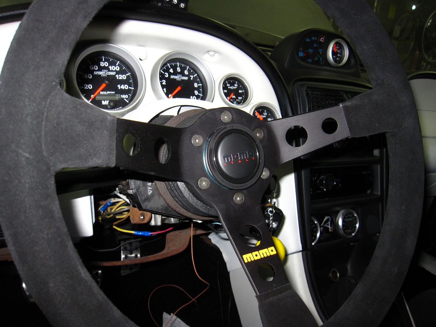
So. You've decided you want an after market steering wheel on your SN95. A Grant, or perhaps a Momo. You drop the coin, remove your stock steering wheel, out comes the clock spring, you put your new wheel hub adapter on, put your new wheel on, and are super digging it....when you realize, "Hmm. What do I do with this horn button?"
Good question! This is what you do with it...
How to get your horn working again with an aftermarket steering wheel
For quite a while I have driven the car with no horn. Thought I could do without it. But not really. And now, I'm installing an aftermarket car alarm, and I prefer the horn over a siren. So, time to get this thing working. I will start this guide assuming you have already removed your stock wheel and clock spring (because those have been long gone on my car and I don't have pics of them). Also, this guide will be specific to a Momo steering wheel and Momo hub adapter, as that is what I have. If you have a different wheel/hub adapter, then the process here - while maybe not exact to your situation - will still be applicable in concept.
1. Order Parts
Assuming you already have a steering wheel and adapter, you will need to order one more thing: a Ford OEM horn contact switch (which you can get here, at AM):

This contact switch has "brushes" that are spring-loaded; they are intended to ride the metal rings on clock springs. My Momo hub adapter has 3 metal rings on the underside of it. The goal is to install this contact switch such that it brushes a ring on the hub adapter so that as the wheel is turned, contact for the horn is maintained. My Momo hub adapter has 3 rings (and thus 3 wires) - but for the horn we only need 1 ring.
2. OEM Contact Switch Mounting Location
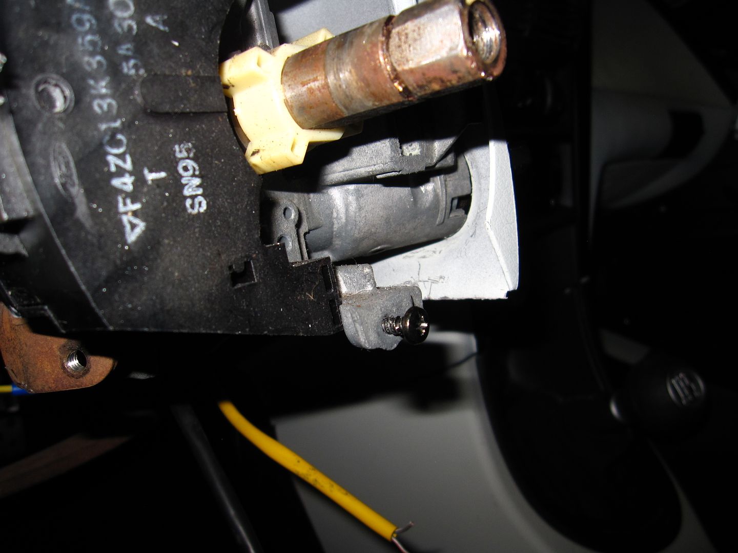
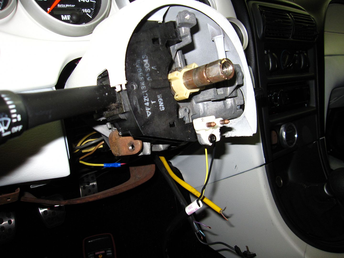
The OEM contact switch is going to be installed in 1 of 3 spots. When the steering wheel is off the column, there are 3 screw holes around the shaft: one at 12 o'clock, one at 6 o'clock, and one more at 3 o'clock. I ended up using the one at 6 o'clock. I found a screw with some coarse thread, and screwed it into the hole (the metal is fairly soft and the screw was able to cut threads as I screwed it in):
3. OEM Horn Switch Modifications
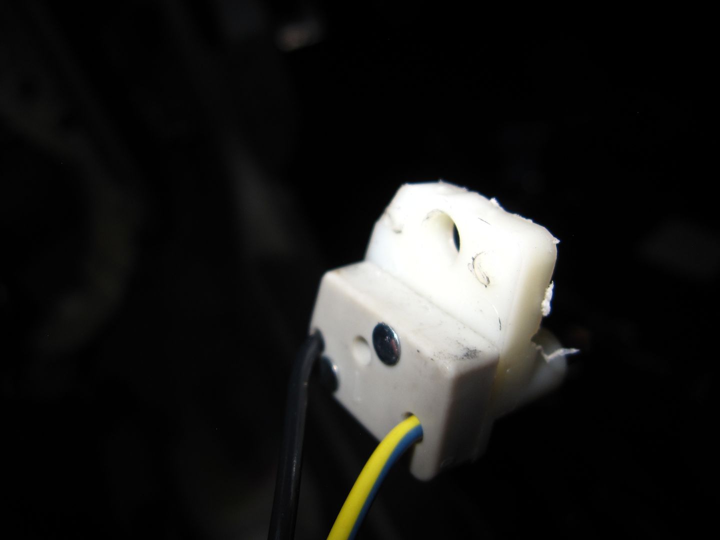
The Ford OEM switch has to be modified to fit in this location. There are two little prongs on the back side of it that must be removed:
And the "tab", where the screw will go, must be trimmed down to allow clearance between the screw head and the hub adapter. I ended up trimming almost half its height using a Dremel:
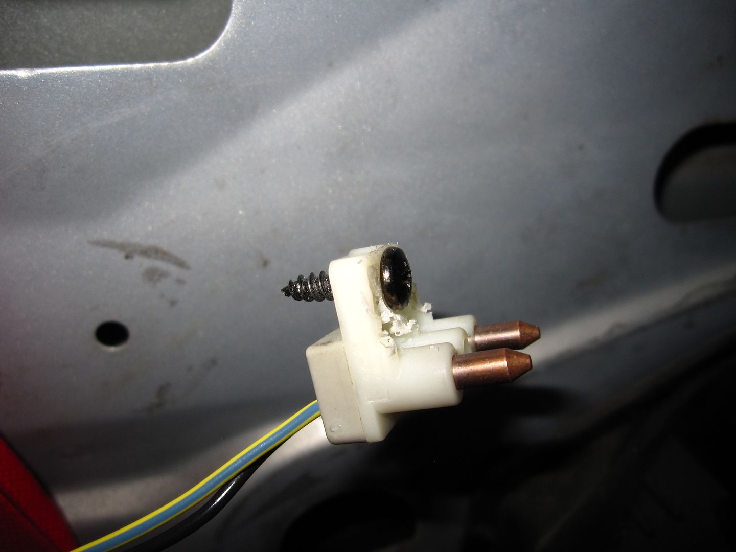
Make sure you go slow in trimming, and do some test fitting along the way. You want to trim just enough off such that the hub adapter does not contact the screw head, but not too much so as to keep strength in the tab that supports the screw. When you get it just right, it will look like this:
Here's a side shot, with the hub adapter on. It's really hard to see, but the white "block" is the switch, and it clears the hub adapter - just barely. Keep in mind that the hub adapter will slide down a hair more on the shaft as you tighten down the hub bolt:
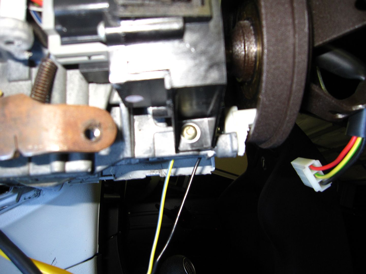
NOTE: As you test fit the switch to the hub adapter, you must make certain that the brushes contact a metal ring on the back side of the hub adapter. If it doesn't, this will not work. If your hub adapter is different, you might have to fab up a little bracket or something to ensure the brushes line up correctly. In my case, with the Momo hub adapter and the location I selected for the switch, it brushes the outer most metal ring. Almost like it was meant to be.
4. Wire It Up
The contact switch has two wires (because it has two brushes). In the orientation that I mount it, both brushes run on the same ring (the outer ring). I highly recommend using both wires. Technically, you could use just 1 wire, as only a single brush needs to make contact. However, if you use both wires, then you have two brushes making contact, and if one should happen to just not quite make contact when the wheel is turning (maybe there's a blemish or rust or something that blocks the brush's contact), then the second brush picks up the slack. So use both wires. You will not need the connector from the contact switch; cut it off and twist the two wires together:
Also, on my car, the horn wire (as can be seen in the pic above) is a small purple one. According to my manual, it's supposed to be purple with an orange stripe - but for the life of me I couldn't see any orange stripe on it. It could just be too small to clearly make out. The wire is maybe 20 AWG. If you touch this wire to ground, your horn should sound. Your car may be different, or have a different color wire (my car is a 95 GT). So be sure to test the wires by touching to ground to be certain you have the horn wire.
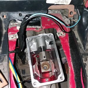
Connect the two wires from the contact switch that you twisted together to the purple wire:

In the above pic, the brown wire connected along with the purple wire is the horn input from my car alarm. If you are wiring in a car alarm, here's your horn signal (it's negative (-) ). If you are just connecting your horn, pretend there is no brown wire.
Find the correct wire on the hub adapter that corresponds to the metal ring the brushes contact. On my hub adapter, it's the red wire. Cut/separate this wire from the other wires. This wire will get a spade connector on it and hook up to the horn button. Use a multimeter to confirm which wire corresponds to which metal ring if you are uncertain.
5. Install Horn Button
In my case, with the Momo steering wheel, there's a metal bracket and wire used to hook the horn up. It looks like this:
This ring is critical. Reinstall the ring and the steering wheel:
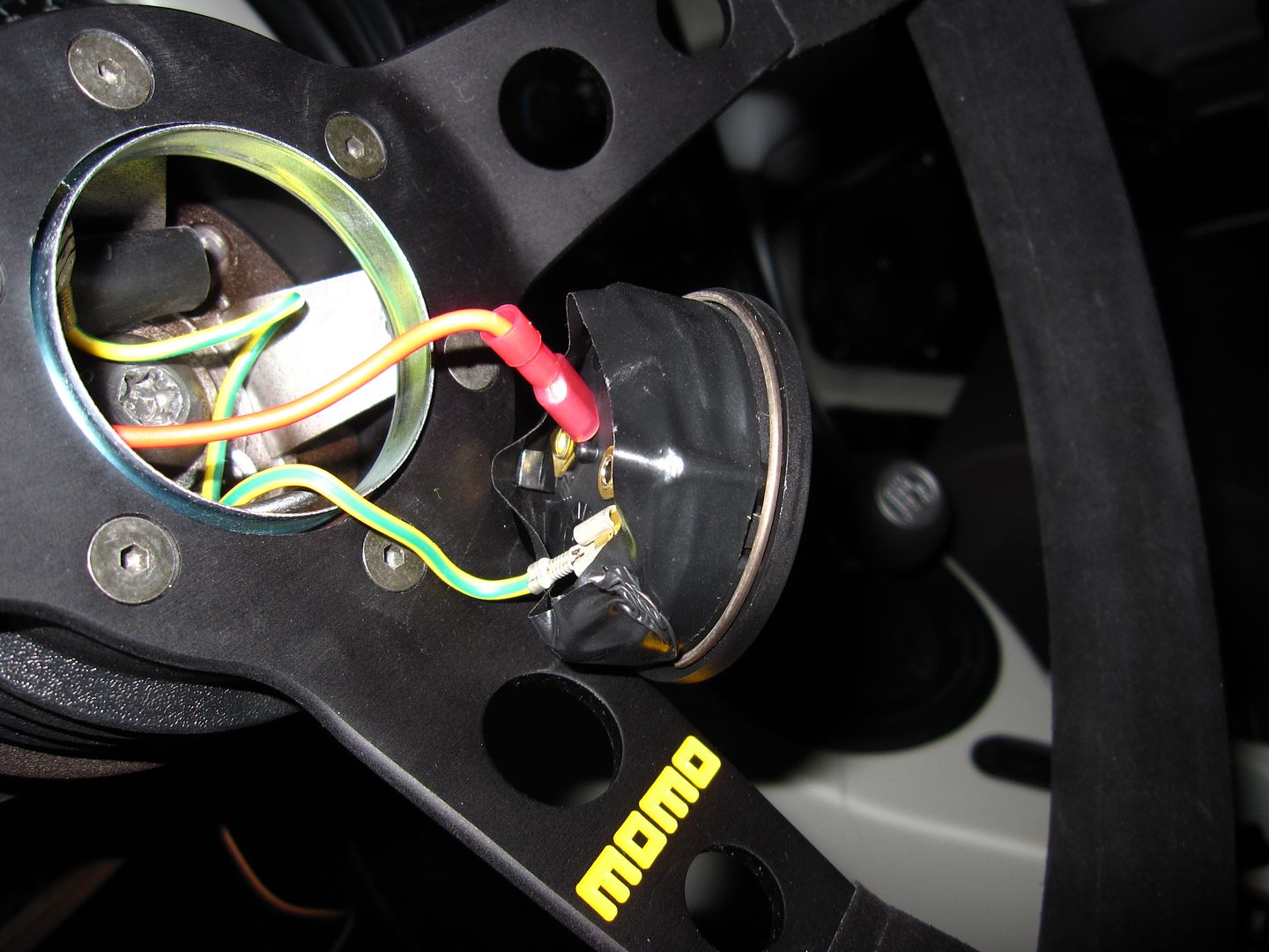
The horn button, on the back of it, has two spade connectors. One wire goes to one, the other wire to the other:
So the circuit works like this: horn ground (purple wire, in my case) from the car, connects to the OEM horn switch, which connects to a metal ring on the hub adapter, which connects to a hub adapter wire (red wire, in my case), which connects to one spade terminal on the horn. The other spade terminal connects to the yellow w/ green stripe wire (came with Momo steering wheel/hub adapter), which connects to the metal bracket (also came with the steering wheel/hub adapter). This metal bracket contacts the metal hub which is actually grounded to the car through the steering shaft. So, when the horn button is pressed, it completes the horn ground circuit from the car to the hub adapter, and your horn sounds.
6. All Done!
And there you have it. Give it a press and test it out. You now have your aftermarket steering wheel, AND a working horn!
Super Bonus Tip
If, like on my steering wheel, the horn button fits just a tad loosely, you can fix this by wrapping some Super 33+ electrical tape around the circumference of the back side of the button. This makes the button just a little bit bigger in diameter, and also adds a little friction, keeping your button nice and secure!
Good luck and have at it!!
Good question! This is what you do with it...
How to get your horn working again with an aftermarket steering wheel
For quite a while I have driven the car with no horn. Thought I could do without it. But not really. And now, I'm installing an aftermarket car alarm, and I prefer the horn over a siren. So, time to get this thing working. I will start this guide assuming you have already removed your stock wheel and clock spring (because those have been long gone on my car and I don't have pics of them). Also, this guide will be specific to a Momo steering wheel and Momo hub adapter, as that is what I have. If you have a different wheel/hub adapter, then the process here - while maybe not exact to your situation - will still be applicable in concept.
1. Order Parts
Assuming you already have a steering wheel and adapter, you will need to order one more thing: a Ford OEM horn contact switch (which you can get here, at AM):
This contact switch has "brushes" that are spring-loaded; they are intended to ride the metal rings on clock springs. My Momo hub adapter has 3 metal rings on the underside of it. The goal is to install this contact switch such that it brushes a ring on the hub adapter so that as the wheel is turned, contact for the horn is maintained. My Momo hub adapter has 3 rings (and thus 3 wires) - but for the horn we only need 1 ring.
2. OEM Contact Switch Mounting Location
The OEM contact switch is going to be installed in 1 of 3 spots. When the steering wheel is off the column, there are 3 screw holes around the shaft: one at 12 o'clock, one at 6 o'clock, and one more at 3 o'clock. I ended up using the one at 6 o'clock. I found a screw with some coarse thread, and screwed it into the hole (the metal is fairly soft and the screw was able to cut threads as I screwed it in):
3. OEM Horn Switch Modifications
The Ford OEM switch has to be modified to fit in this location. There are two little prongs on the back side of it that must be removed:
And the "tab", where the screw will go, must be trimmed down to allow clearance between the screw head and the hub adapter. I ended up trimming almost half its height using a Dremel:
Make sure you go slow in trimming, and do some test fitting along the way. You want to trim just enough off such that the hub adapter does not contact the screw head, but not too much so as to keep strength in the tab that supports the screw. When you get it just right, it will look like this:
Here's a side shot, with the hub adapter on. It's really hard to see, but the white "block" is the switch, and it clears the hub adapter - just barely. Keep in mind that the hub adapter will slide down a hair more on the shaft as you tighten down the hub bolt:
NOTE: As you test fit the switch to the hub adapter, you must make certain that the brushes contact a metal ring on the back side of the hub adapter. If it doesn't, this will not work. If your hub adapter is different, you might have to fab up a little bracket or something to ensure the brushes line up correctly. In my case, with the Momo hub adapter and the location I selected for the switch, it brushes the outer most metal ring. Almost like it was meant to be.
4. Wire It Up
The contact switch has two wires (because it has two brushes). In the orientation that I mount it, both brushes run on the same ring (the outer ring). I highly recommend using both wires. Technically, you could use just 1 wire, as only a single brush needs to make contact. However, if you use both wires, then you have two brushes making contact, and if one should happen to just not quite make contact when the wheel is turning (maybe there's a blemish or rust or something that blocks the brush's contact), then the second brush picks up the slack. So use both wires. You will not need the connector from the contact switch; cut it off and twist the two wires together:
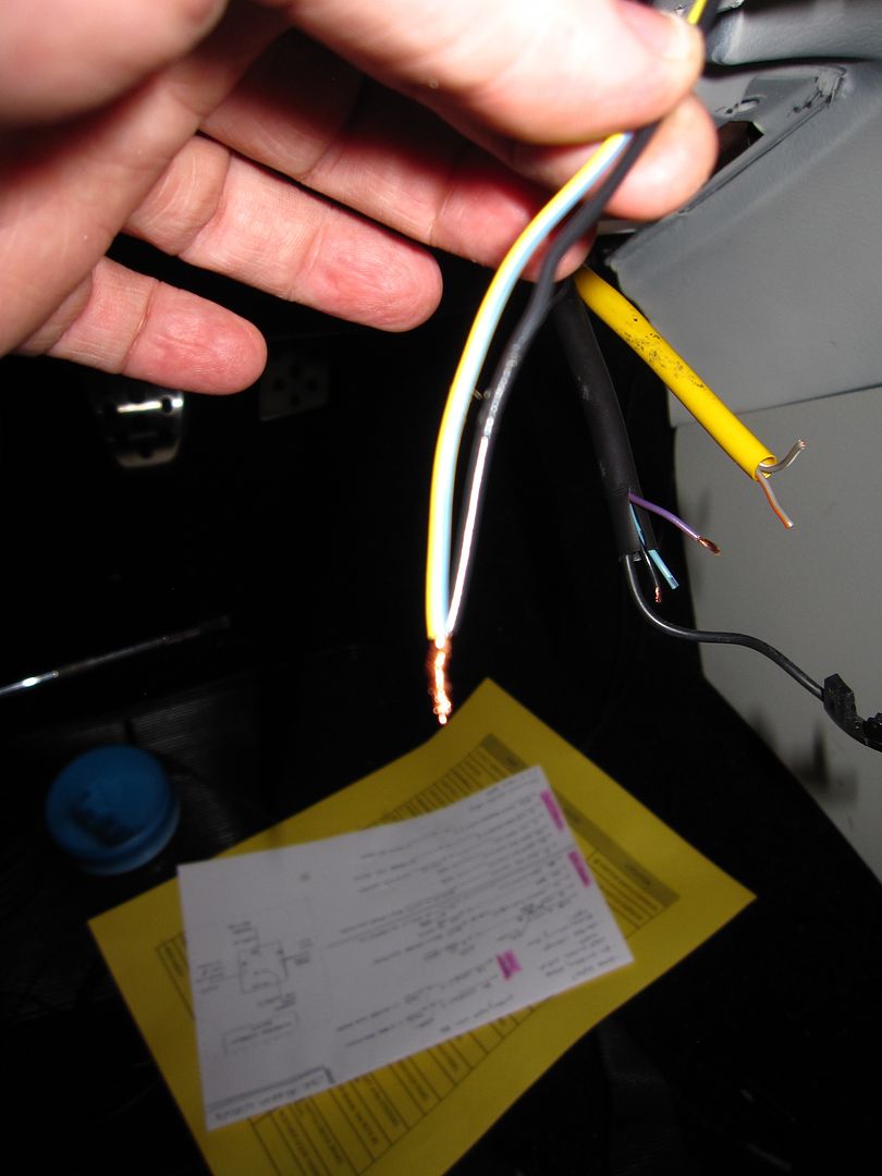
Also, on my car, the horn wire (as can be seen in the pic above) is a small purple one. According to my manual, it's supposed to be purple with an orange stripe - but for the life of me I couldn't see any orange stripe on it. It could just be too small to clearly make out. The wire is maybe 20 AWG. If you touch this wire to ground, your horn should sound. Your car may be different, or have a different color wire (my car is a 95 GT). So be sure to test the wires by touching to ground to be certain you have the horn wire.
Connect the two wires from the contact switch that you twisted together to the purple wire:
In the above pic, the brown wire connected along with the purple wire is the horn input from my car alarm. If you are wiring in a car alarm, here's your horn signal (it's negative (-) ). If you are just connecting your horn, pretend there is no brown wire.
Find the correct wire on the hub adapter that corresponds to the metal ring the brushes contact. On my hub adapter, it's the red wire. Cut/separate this wire from the other wires. This wire will get a spade connector on it and hook up to the horn button. Use a multimeter to confirm which wire corresponds to which metal ring if you are uncertain.
5. Install Horn Button
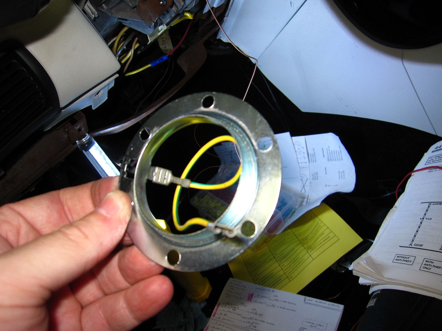
In my case, with the Momo steering wheel, there's a metal bracket and wire used to hook the horn up. It looks like this:
This ring is critical. Reinstall the ring and the steering wheel:
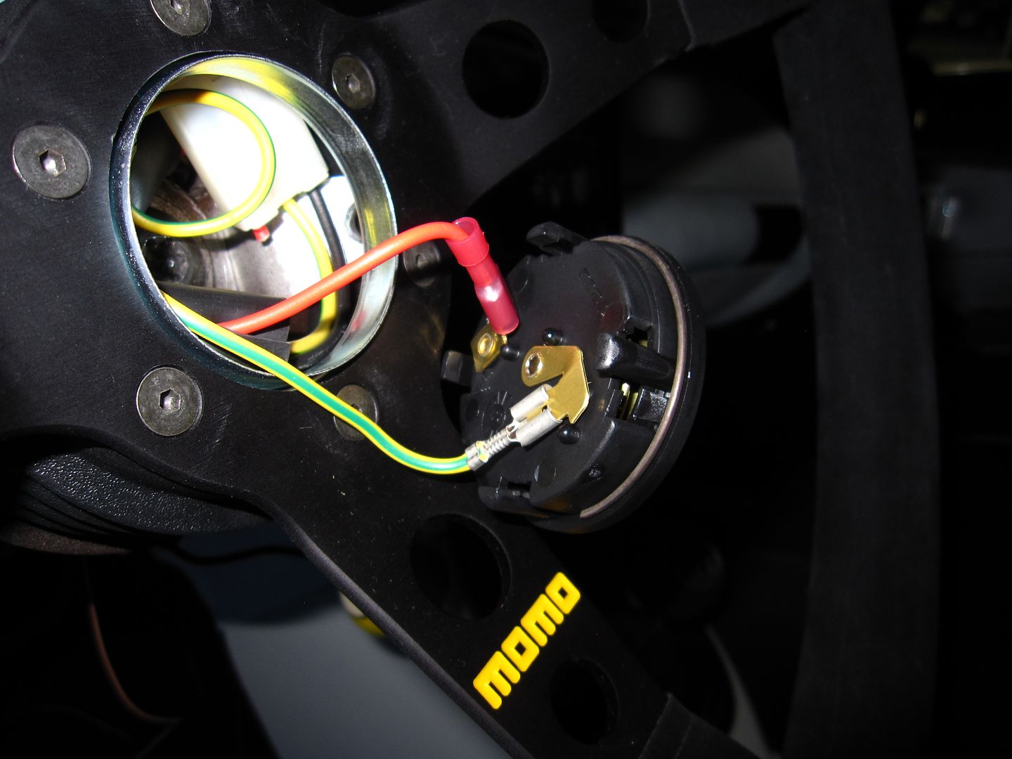
The horn button, on the back of it, has two spade connectors. One wire goes to one, the other wire to the other:
So the circuit works like this: horn ground (purple wire, in my case) from the car, connects to the OEM horn switch, which connects to a metal ring on the hub adapter, which connects to a hub adapter wire (red wire, in my case), which connects to one spade terminal on the horn. The other spade terminal connects to the yellow w/ green stripe wire (came with Momo steering wheel/hub adapter), which connects to the metal bracket (also came with the steering wheel/hub adapter). This metal bracket contacts the metal hub which is actually grounded to the car through the steering shaft. So, when the horn button is pressed, it completes the horn ground circuit from the car to the hub adapter, and your horn sounds.
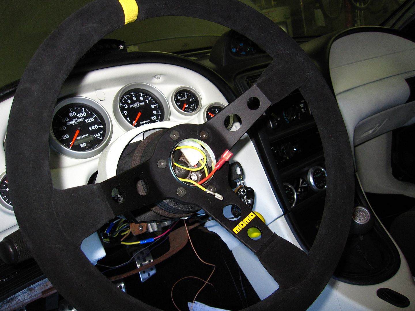
6. All Done!
And there you have it. Give it a press and test it out. You now have your aftermarket steering wheel, AND a working horn!
Super Bonus Tip
If, like on my steering wheel, the horn button fits just a tad loosely, you can fix this by wrapping some Super 33+ electrical tape around the circumference of the back side of the button. This makes the button just a little bit bigger in diameter, and also adds a little friction, keeping your button nice and secure!
Good luck and have at it!!