Manson31
New Member
Hi, I'm new here and this is my first post.
Hello to all and hope I'm not repeating anything that's been done before.
I'm from the UK. It isn't so easy to get performance parts for Mustangs over here but I finally got my hands on a Kenne Bell non-intercooled 6psi blower kit....
I’ll get straight on to the install:
First off, I will say that if you’re attempting a similar task yourself (on your own); allow at least 2 weekends to do it.
I had help all weekend and it took us approximately 35 man-hours in total (not being sexist, we are both men).
Also, I installed the non-intercooled kit. The intercooled version has lots of extra steps as it’s a water / air setup and needs an additional coolant tank, pump, matrix etc. I would guess another 8 hours at least to fit that.
Secondly, I have to say that it is not a difficult job. My mate and I are what I would call skilled amateurs, having never had any formal mechanical training nor ever having earned our living as mechanics.
I have a fairly well equipped garage and a good variety of tools. Of the two of us, Dave is by far the most skilled at electrics although he admitted that the electrical skills needed to install the blower were minimal i.e. cut about 10 wires, solder new pieces in and heat shrink the joints.
To be fair, the Kenne Bell instructions are probably the best I’ve ever used with pictures provided for each step. The only possible improvement would be to provide them as a pdf so you could see them in colour and enlarge them if necessary. My advice is not to rush anything. Read the manual, make sure you understand what you’re doing and only then take action.
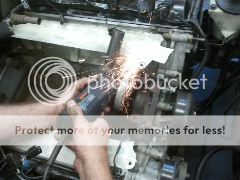
We did clean up a lot of the components, wiring and connectors as we went. This slowed the job down but the end result is worth it: Who wants a shiny new blower sitting on top of a grubby engine?
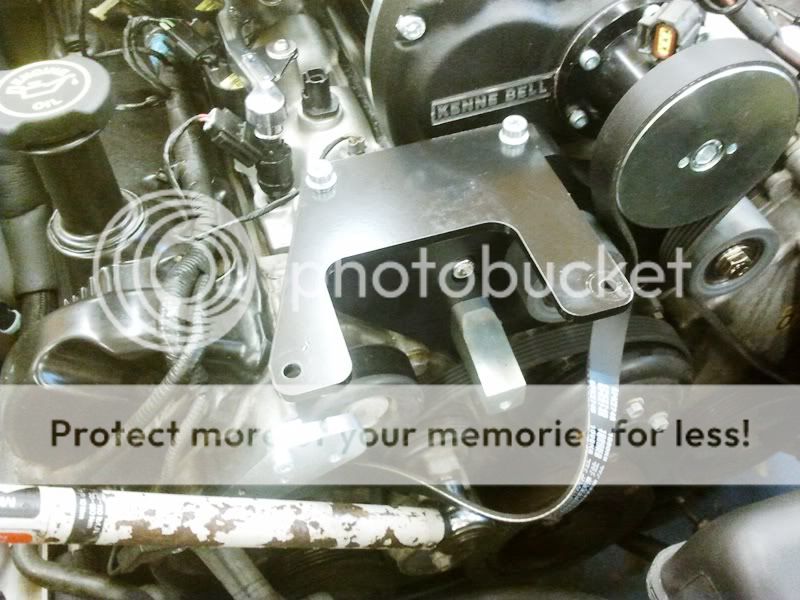
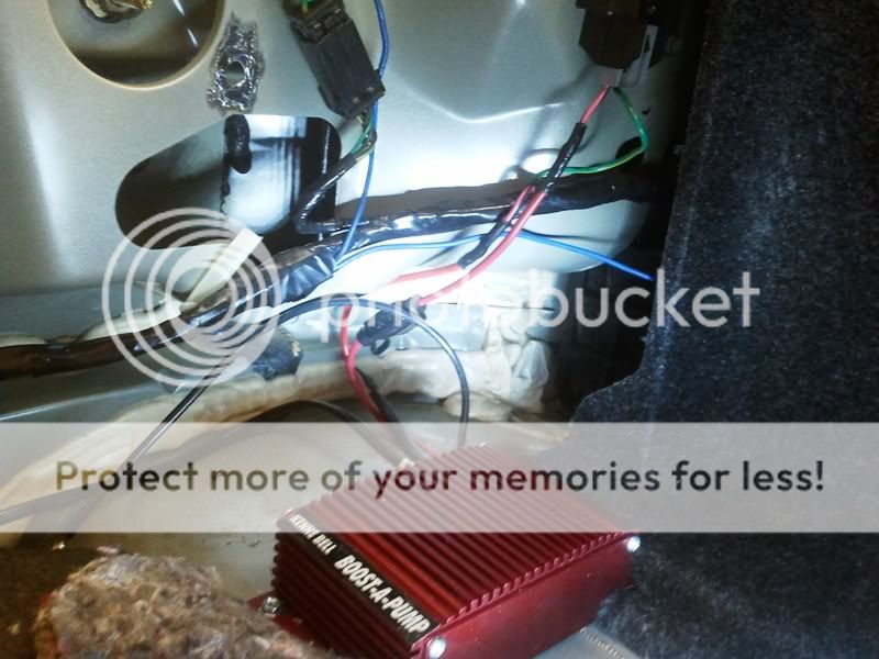
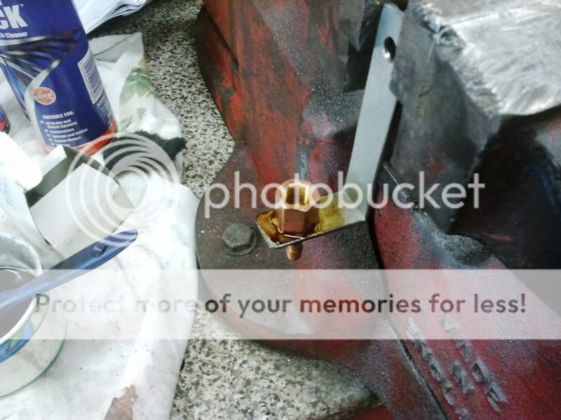
KB deserves its excellent reputation. The kit was 99.99% complete (even down to including lots of zip ties and a small roll of solder): We only had to fabricate one small / simple bracket to carry the ‘Boost-A-Pump’ boost sensor but that could have been just zip-tied somewhere instead. Top marks for KB so far!
Excuse the quality of some of the pics: basic camera phone only and no flash available. All comments apply to the picture above them.
Okay here we go…
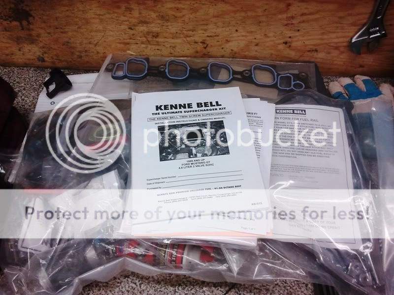
Above is the main bag of components and the 104 page instruction manual sat on the bench.
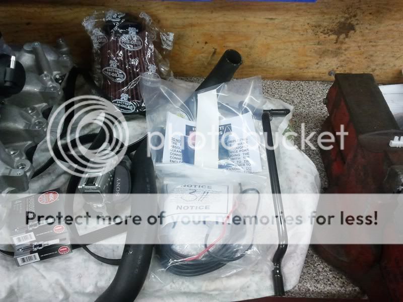
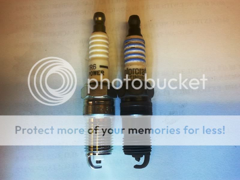
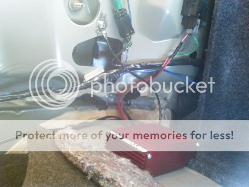
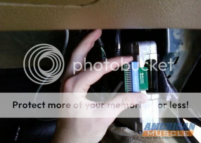
In the above pic you can see the new heater pipes, the KB Boost-A-Pump (more later) and the 4 bank piggy back chip which KB programs according to your particular vehicle. The above are all included in the kit. Not included are the one stage cooler spark plugs, K&N filter and camcorder (lol).
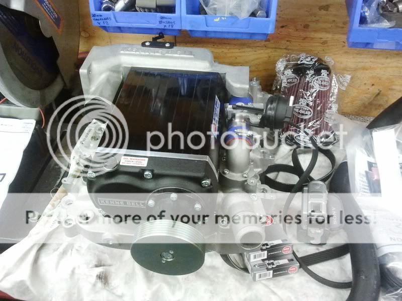
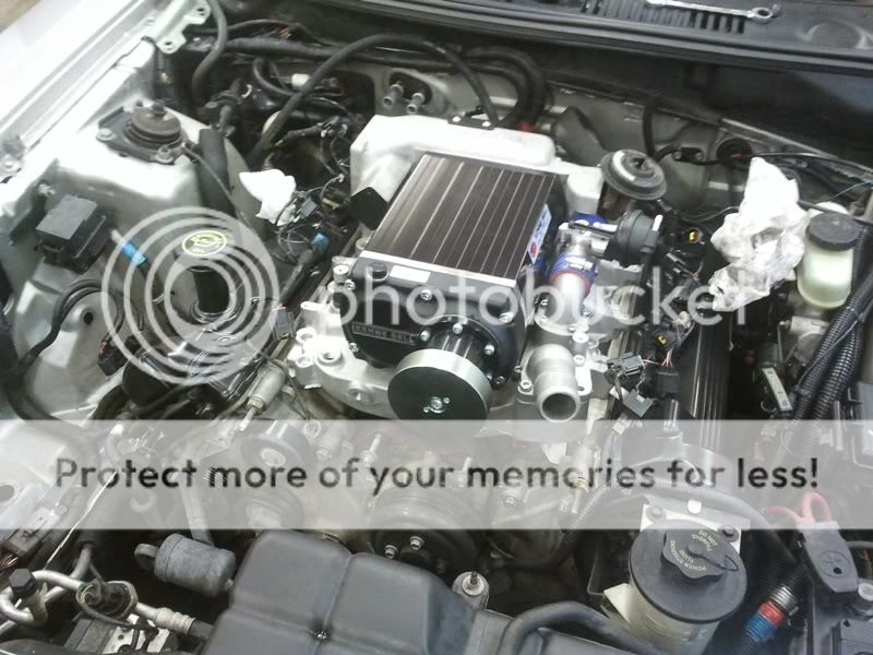
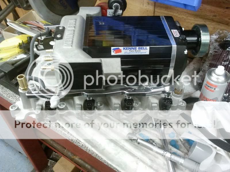
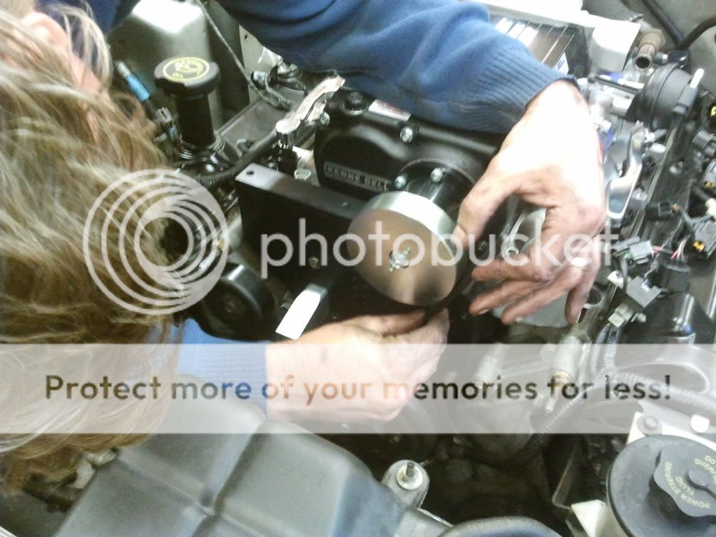
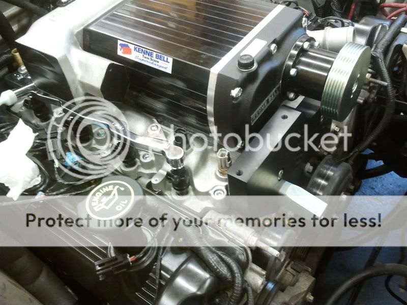
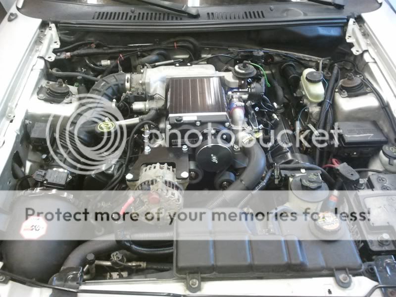
Finally, the supercharger unit, inlet manifold, thermostat, housing and bypass mechanism. This little lot comes pre-assembled with only a few items to add before fitting.
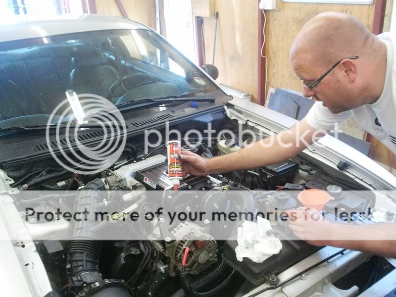
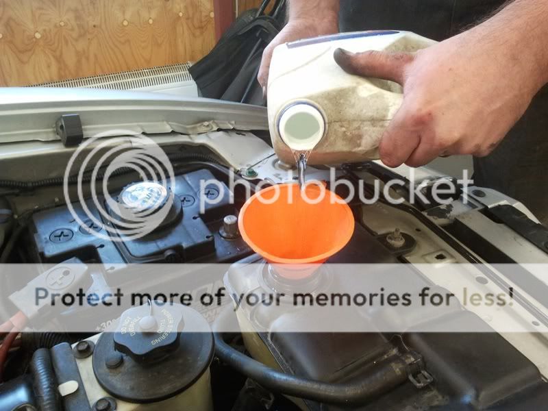
First real step is draining the coolant and disconnecting the battery. There is a 19mm nylon hex bolt at the front of the passenger side front wheel arch. Put a large bowl under it and undo it to drain the coolant. Battery terminals need an 8mm spanner.
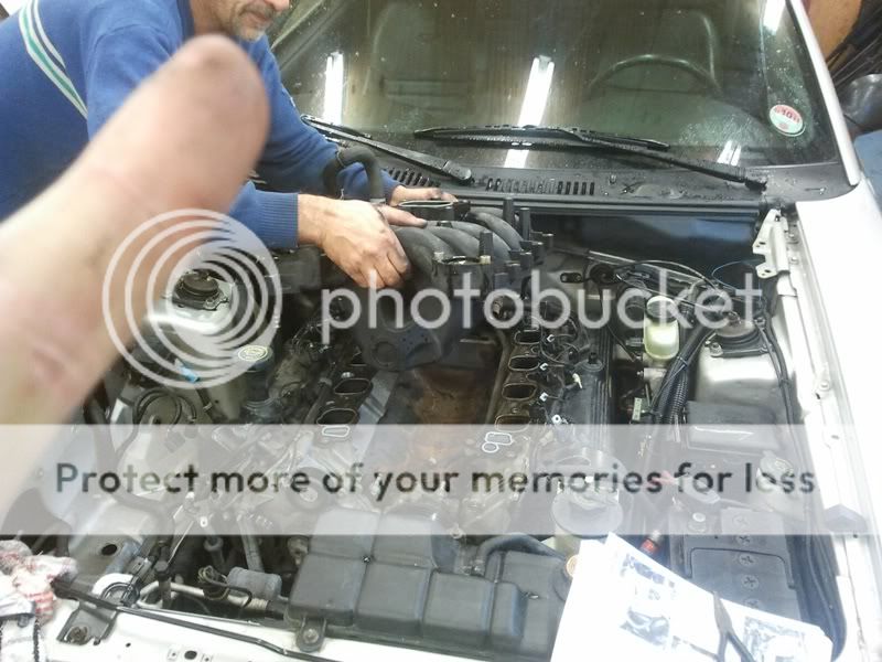
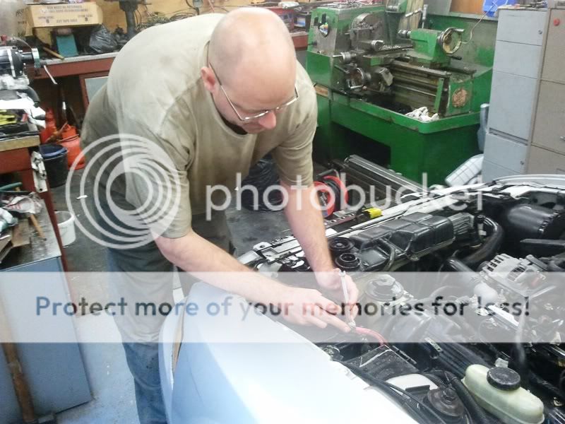
We decided to take the bonnet off. Note – some models require strut brace assembly to be removed also, but not mine.
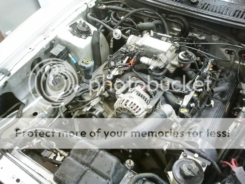
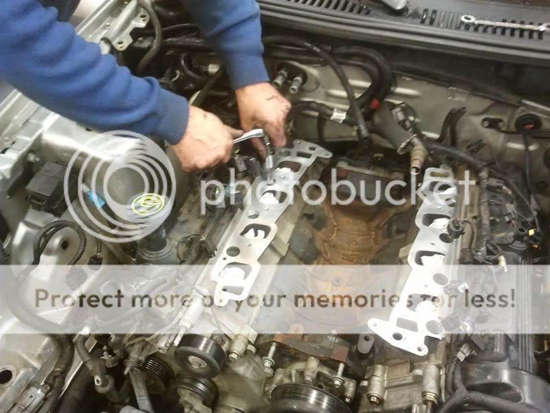
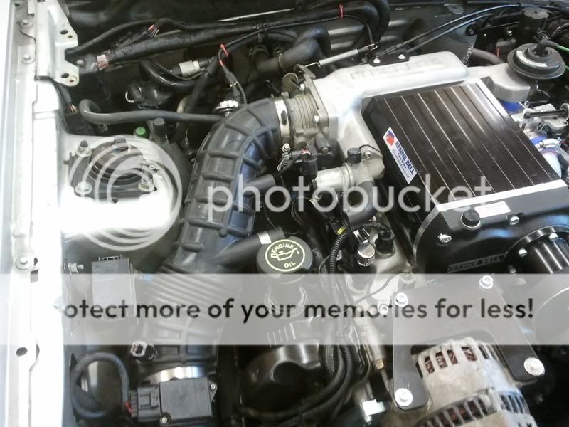
Intake assembly removed. Mine has a separate MAF and IAC sensor whereas on later models these are combined. Also some of the crankcase venting hoses have been removed.
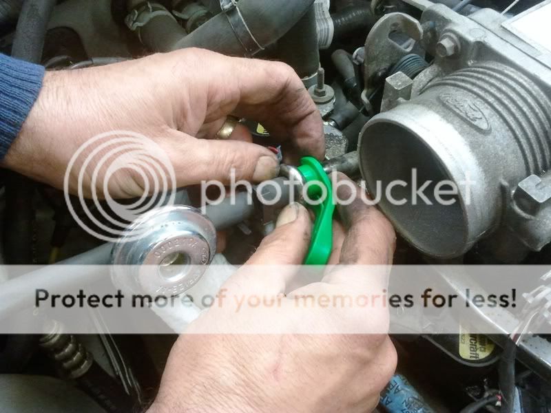
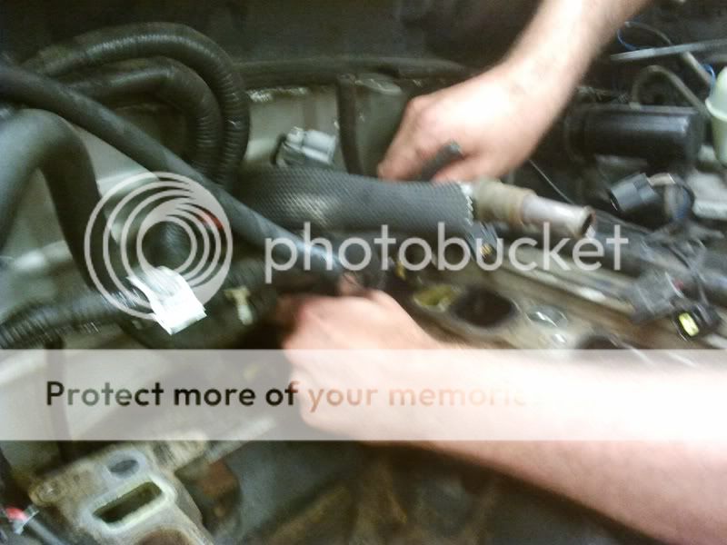
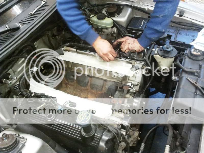
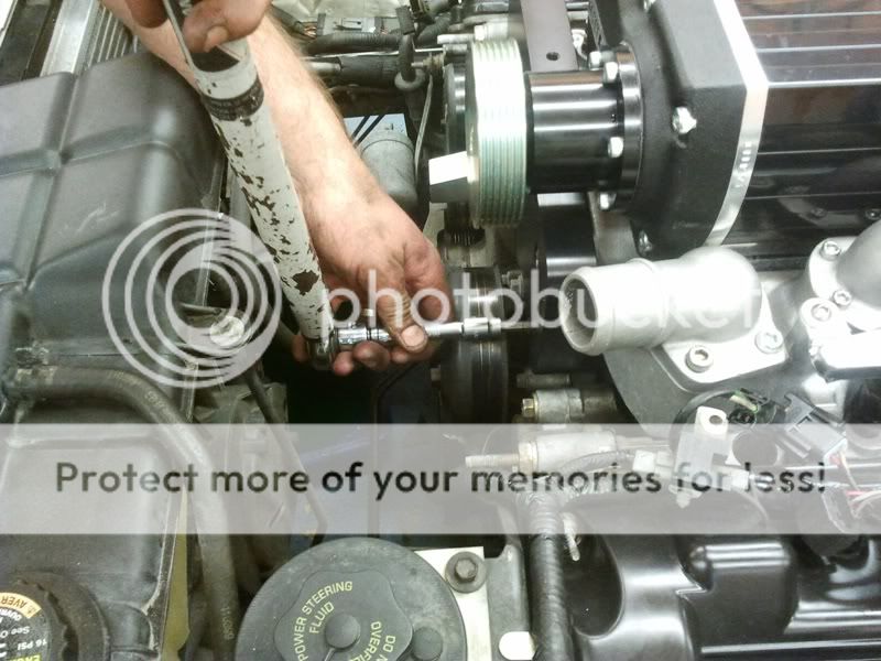
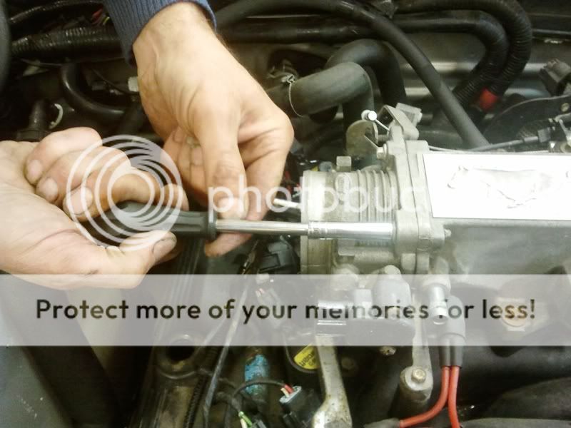
Above, we’re using a 5/8 quick disconnect tool to separate the fuel rails from the fuel line. I love the engineering simplicity / beauty of these things!
(Make sure you have released the fuel pressure in the rails by using the tyre type valve on the L/H rail before you separate the fuel line.)
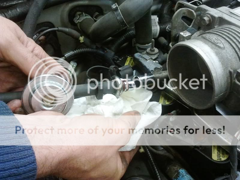
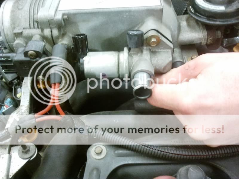
Fuel line separated – note double o-ring seal.
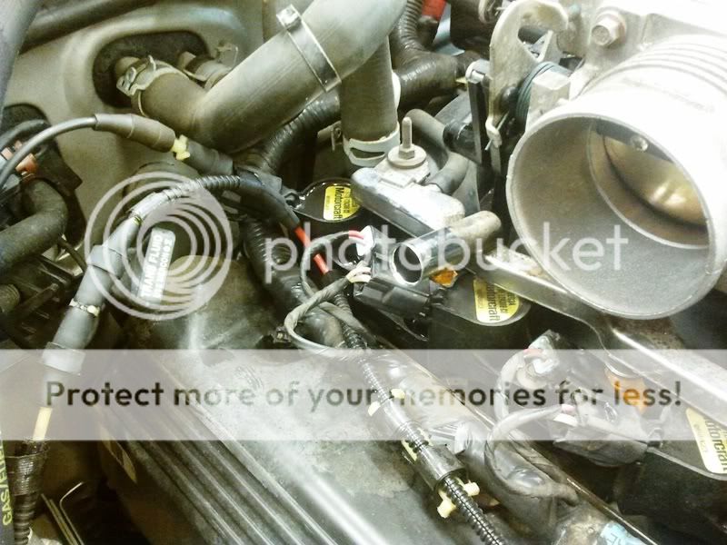
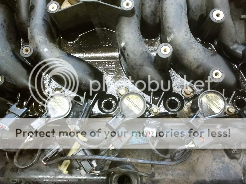
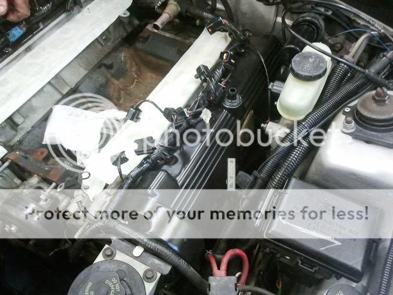
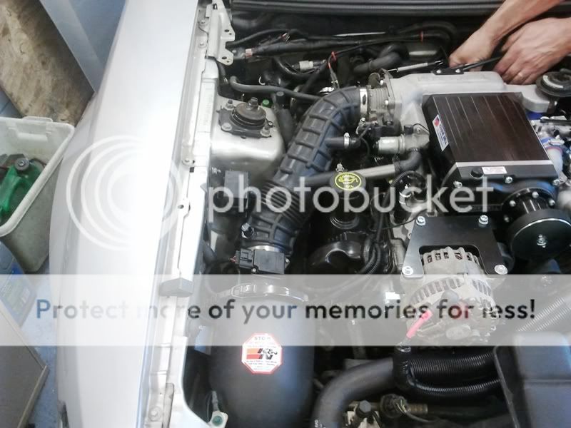
Above: Fuel line disconnected and ticked out of the way. Note filthy valve cover and rusty old fuel rail.
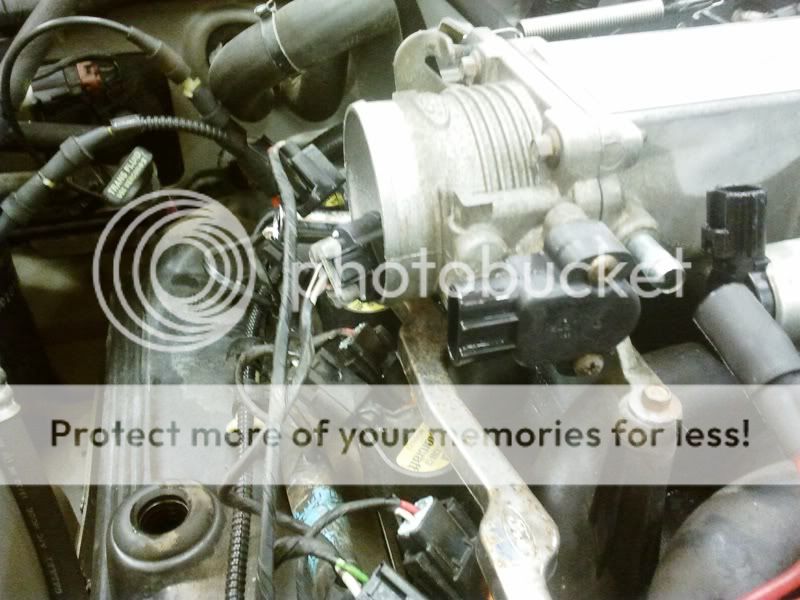
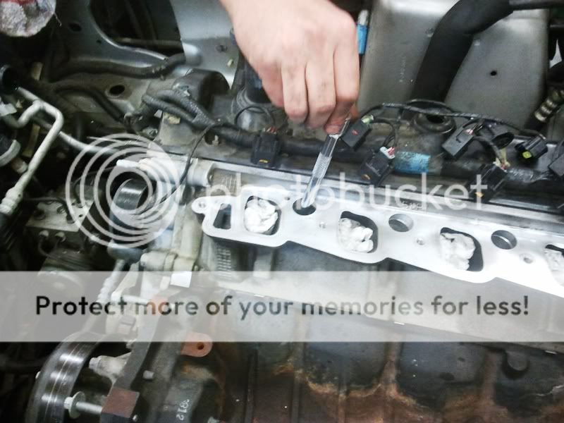
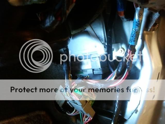
Various connectors unplugged. Take your time figuring out how each one separates. On this car, just one of the fuel injector plugs was broken but on my ’96 most had been broken at one time or another. There is no need for this. When done correctly, all engine plugs slide out easily!
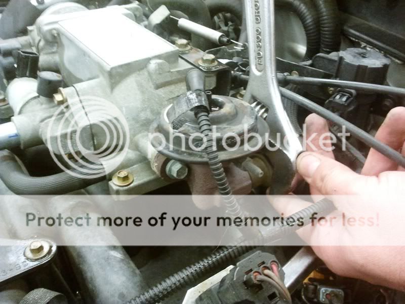
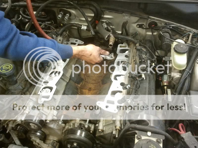
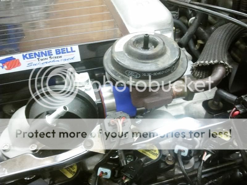
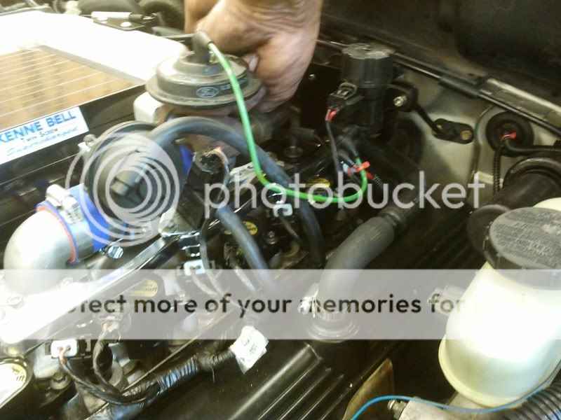
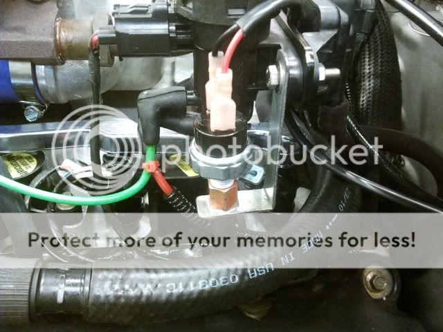
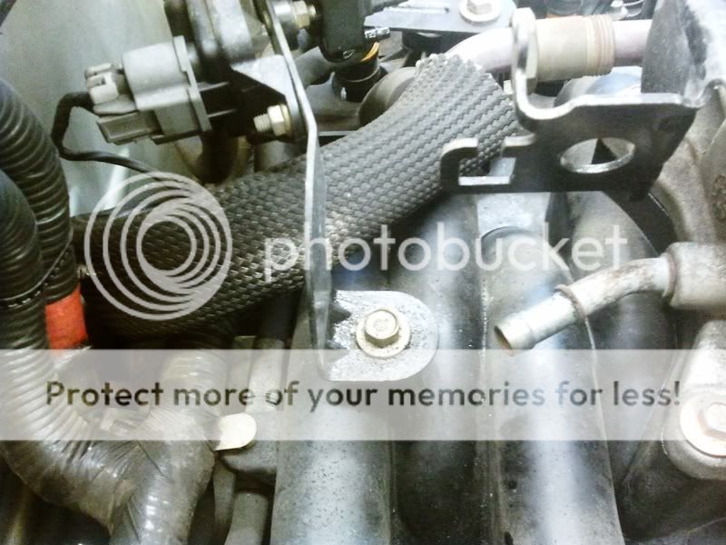
I’m not normally a fan of adjustable spanners but made an exception when it cam to the EGR pipe. Above I have already disconnected the vacuum connection on top of the valve.
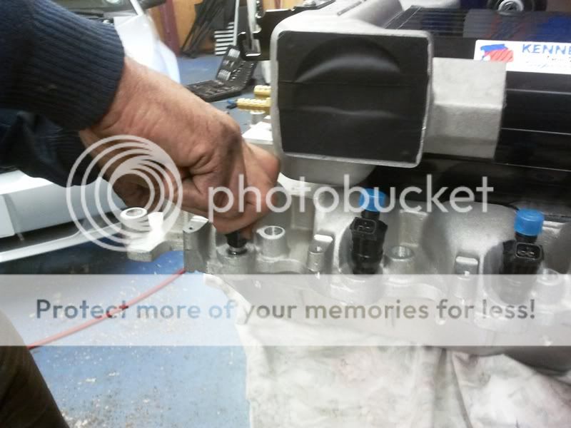
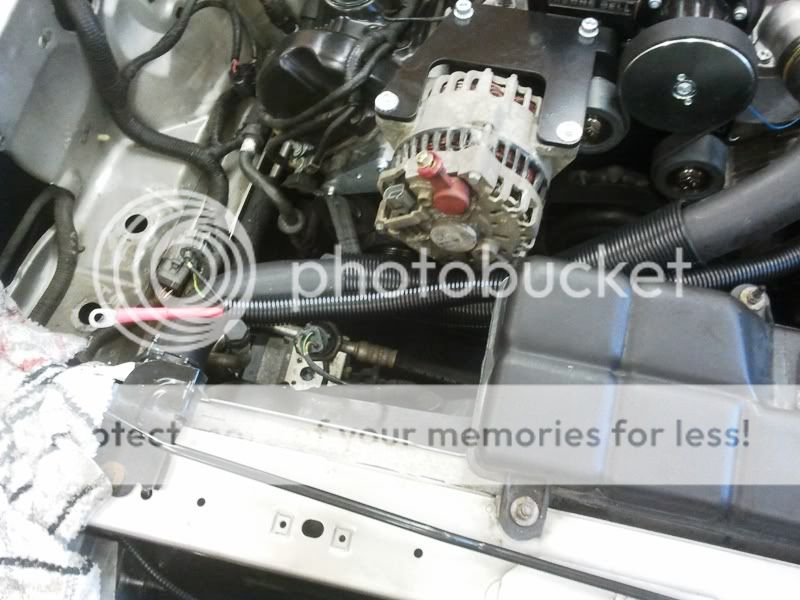
Directly below the EGR valve is the fuel rail pressure transducer. More on it later…
Hello to all and hope I'm not repeating anything that's been done before.
I'm from the UK. It isn't so easy to get performance parts for Mustangs over here but I finally got my hands on a Kenne Bell non-intercooled 6psi blower kit....
I’ll get straight on to the install:
First off, I will say that if you’re attempting a similar task yourself (on your own); allow at least 2 weekends to do it.
I had help all weekend and it took us approximately 35 man-hours in total (not being sexist, we are both men).
Also, I installed the non-intercooled kit. The intercooled version has lots of extra steps as it’s a water / air setup and needs an additional coolant tank, pump, matrix etc. I would guess another 8 hours at least to fit that.
Secondly, I have to say that it is not a difficult job. My mate and I are what I would call skilled amateurs, having never had any formal mechanical training nor ever having earned our living as mechanics.
I have a fairly well equipped garage and a good variety of tools. Of the two of us, Dave is by far the most skilled at electrics although he admitted that the electrical skills needed to install the blower were minimal i.e. cut about 10 wires, solder new pieces in and heat shrink the joints.
To be fair, the Kenne Bell instructions are probably the best I’ve ever used with pictures provided for each step. The only possible improvement would be to provide them as a pdf so you could see them in colour and enlarge them if necessary. My advice is not to rush anything. Read the manual, make sure you understand what you’re doing and only then take action.
We did clean up a lot of the components, wiring and connectors as we went. This slowed the job down but the end result is worth it: Who wants a shiny new blower sitting on top of a grubby engine?
KB deserves its excellent reputation. The kit was 99.99% complete (even down to including lots of zip ties and a small roll of solder): We only had to fabricate one small / simple bracket to carry the ‘Boost-A-Pump’ boost sensor but that could have been just zip-tied somewhere instead. Top marks for KB so far!
Excuse the quality of some of the pics: basic camera phone only and no flash available. All comments apply to the picture above them.
Okay here we go…
Above is the main bag of components and the 104 page instruction manual sat on the bench.
In the above pic you can see the new heater pipes, the KB Boost-A-Pump (more later) and the 4 bank piggy back chip which KB programs according to your particular vehicle. The above are all included in the kit. Not included are the one stage cooler spark plugs, K&N filter and camcorder (lol).
Finally, the supercharger unit, inlet manifold, thermostat, housing and bypass mechanism. This little lot comes pre-assembled with only a few items to add before fitting.
First real step is draining the coolant and disconnecting the battery. There is a 19mm nylon hex bolt at the front of the passenger side front wheel arch. Put a large bowl under it and undo it to drain the coolant. Battery terminals need an 8mm spanner.
We decided to take the bonnet off. Note – some models require strut brace assembly to be removed also, but not mine.
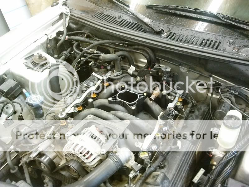
Intake assembly removed. Mine has a separate MAF and IAC sensor whereas on later models these are combined. Also some of the crankcase venting hoses have been removed.
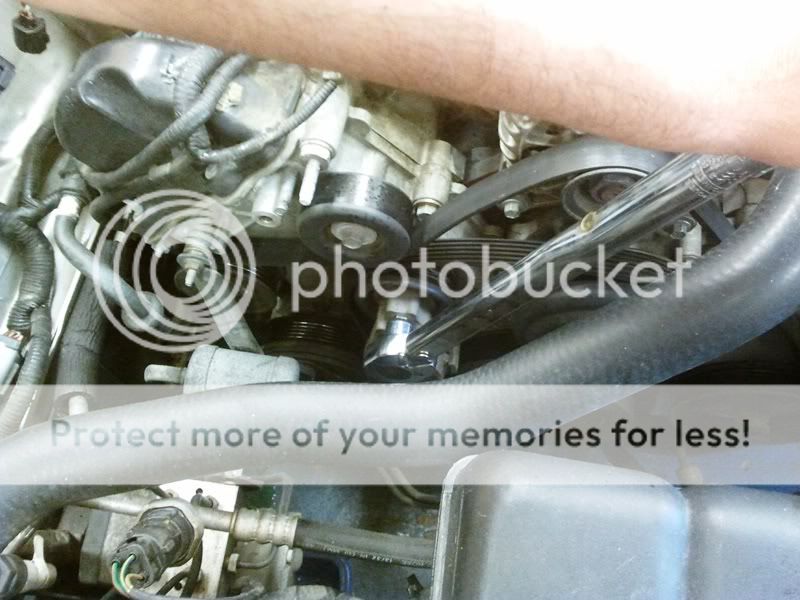
Above, we’re using a 5/8 quick disconnect tool to separate the fuel rails from the fuel line. I love the engineering simplicity / beauty of these things!
(Make sure you have released the fuel pressure in the rails by using the tyre type valve on the L/H rail before you separate the fuel line.)
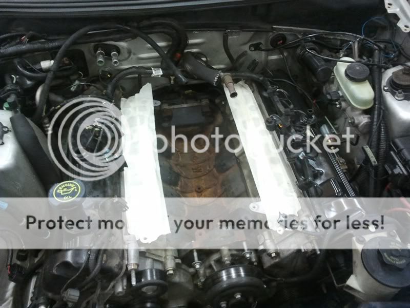
Fuel line separated – note double o-ring seal.
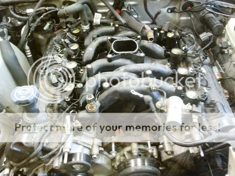
Above: Fuel line disconnected and ticked out of the way. Note filthy valve cover and rusty old fuel rail.
Various connectors unplugged. Take your time figuring out how each one separates. On this car, just one of the fuel injector plugs was broken but on my ’96 most had been broken at one time or another. There is no need for this. When done correctly, all engine plugs slide out easily!
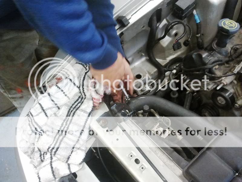
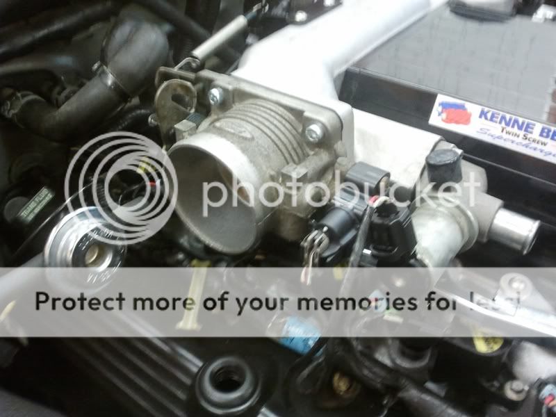
I’m not normally a fan of adjustable spanners but made an exception when it cam to the EGR pipe. Above I have already disconnected the vacuum connection on top of the valve.
Directly below the EGR valve is the fuel rail pressure transducer. More on it later…
")