mineralgreygt
Member
Not sure if this is being posted in the right section please feel free to move it if not.
So after much digging on the net and calling vendors I could not find a good DIY MOMO steering wheel and hub installation so I took matters into my own hands. So Here's what I purchased
http://www.americanmuscle.com/momo-race-steering-wheel.html
http://www.americanmuscle.com/steering-wheel-hub-8404.html
http://www.americanmuscle.com/ford-horn-contact-switch.html
My main concern was how to hook up the ford horn contact switch properly, and with zero info on it anywhere, or at least that I could find I went to work.
First things first, to do this install you'll have to remove the battery connections and let the car sit for at least 1/2hour because you'll be working with the air bag system and the last thing you want is that thing to go off in your face. Once the cables were free from the battery I took both battery cables and tied the terminals together with a bolt and nut to quickly dissipate the air bag capacitor's charge. When you shut your car off the airbag system has a capacitor which holds a charge for some period of time and keeps the airbag system energized until it drains out.
Next you'll need to remove the plastic knee panel and the metal knee panel under the steering wheel, they both have two bolts holding them in place, the plastic one however has some clips up top as well, should come off real easy.
you can follow these instructions here for removing the steering wheel FR500 Mustang Steering Wheel Installation Guide | AmericanMuscle
I also used this video to get to the clockspring assembly https://www.youtube.com/watch?v=0GUIZuIVxxU
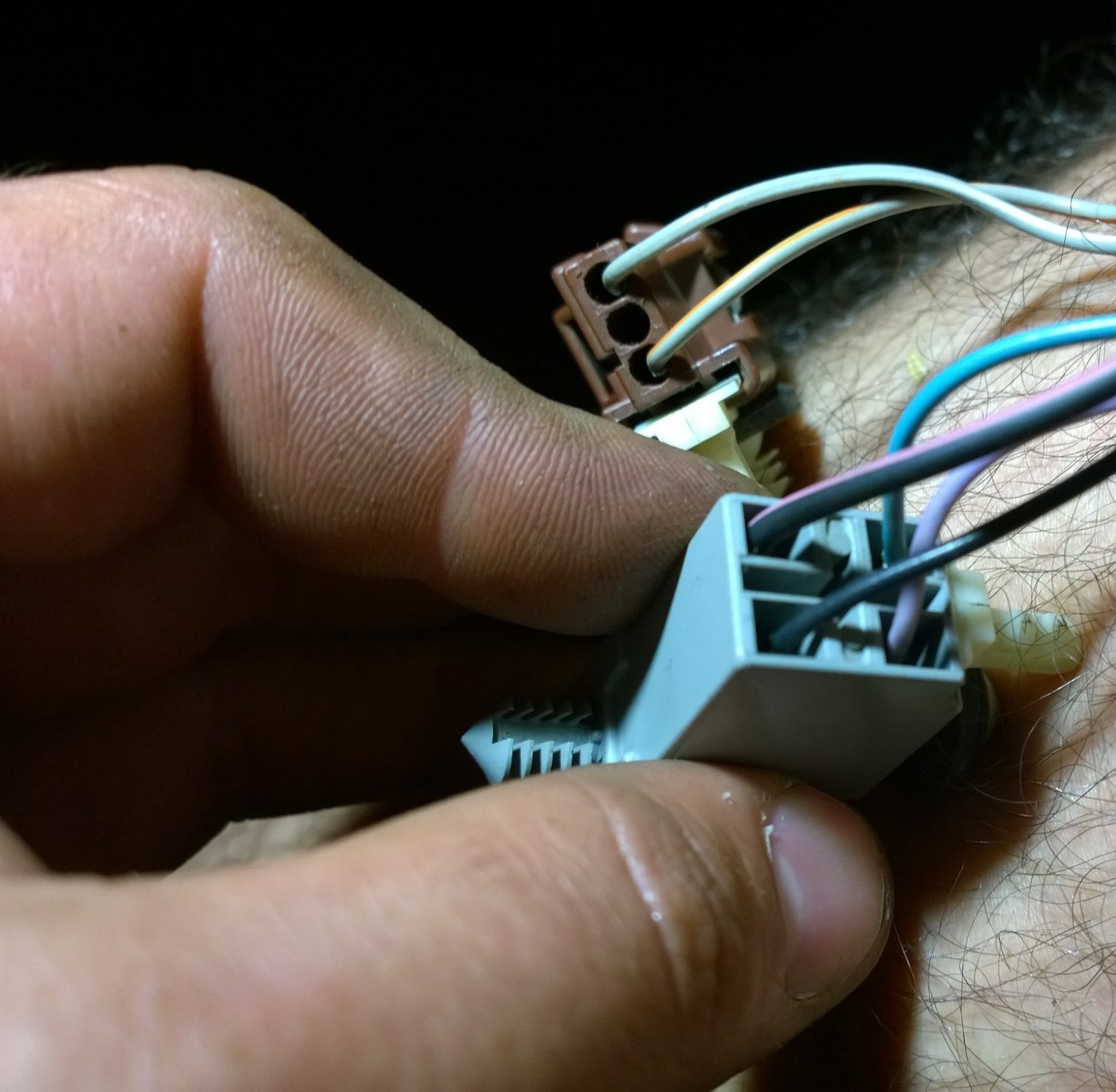
I did this part a little differently from the video. I didn't remove the key tumbler I kept all of that in place including the PATS box/connector. I undid the air bag connector (brown) and the horn/cruise control connector (light grey)
If you watch the video he points out where all the clock springs clips are for removal which can easily be removed with the top half of the steering column in place. Another thing he mentions is that there are 3 screws holding the two column halves together but in our cars there is 4. Another thing I did differently is I took all the pins out of the connectors coming off the clock spring assembly going into the main harness. The reason for this was to be able to draw the wires through the opening under the key tumbler without worrying about the connectors getting caught on the backside, if you don't remove the pins from the connector you wont be able to pull the harness through the opening.
You'll need a small flat blade screw driver, looking at the light grey connector if you look inside you can see little tabs that can be bent. While holding the wire to be removed and pulling on it simultaneously, use the screw driver to free it. The airbag connector is a little different, first you have to remove the red safety clip inside the connector, this can be done by flipping to the backside of the connector there is a little slot the screwdriver can fit in and push up on the red safety tab causing it to come out where the pins are. The pin removal is than similar to the other connector.
Once that's done you can pull all the wires through the opening. There is one wire left that's keeping the hole assembly still attached and that's the black wire with a pink stripe going to the key tumbler, this wire controls the door chime when you have the key in the ignition. You can either disassemble the tumbler and its corresponding components to remove it intact or just cut it, which is what I did.
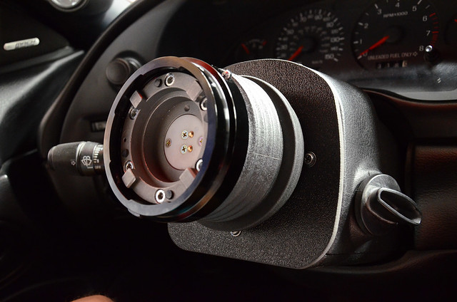
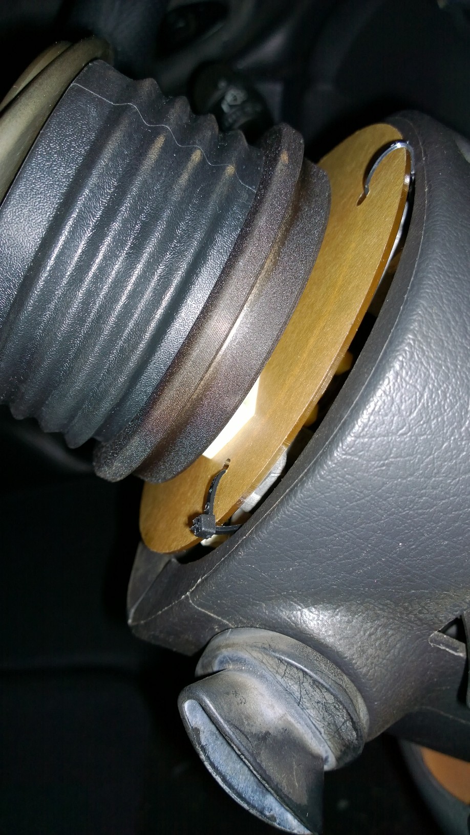
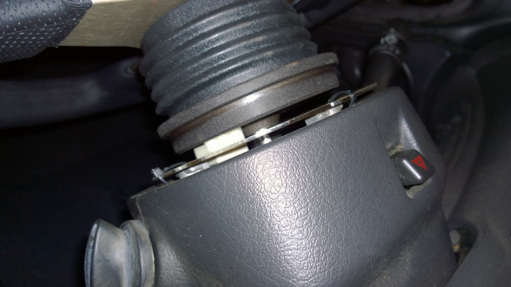
Once the clock spring assembly was removed I noticed there were three holes located on the steering column. I took some measurements of the hole locations with respect to the steering shaft and sketched up a bracket. I have access to a cnc laser cutter so I cut mine out of 1/8" acrylic. I measured the two prong horn switch connector and mounted it to the bracket utilizing its two pins and hole to fasten it to the plate I just cut out. 1/8" is probably the thickest you want to make it other wise the the prongs will bottom out and you could potentially have the connector housing rubbing on the MOMO hub's slip rings. Heres is a dimension drawing https://www.scribd.com/doc/284213720/Mounting-Plate it should be 1:1 so you can print it and use it as a template or just use the dimension, its on an 11 x 17 paper format . I forgot to take a picture of the just the connector and the bracket installed. Don't mind the zip ties I didn't have the right size screws laying around but here's the finished product.
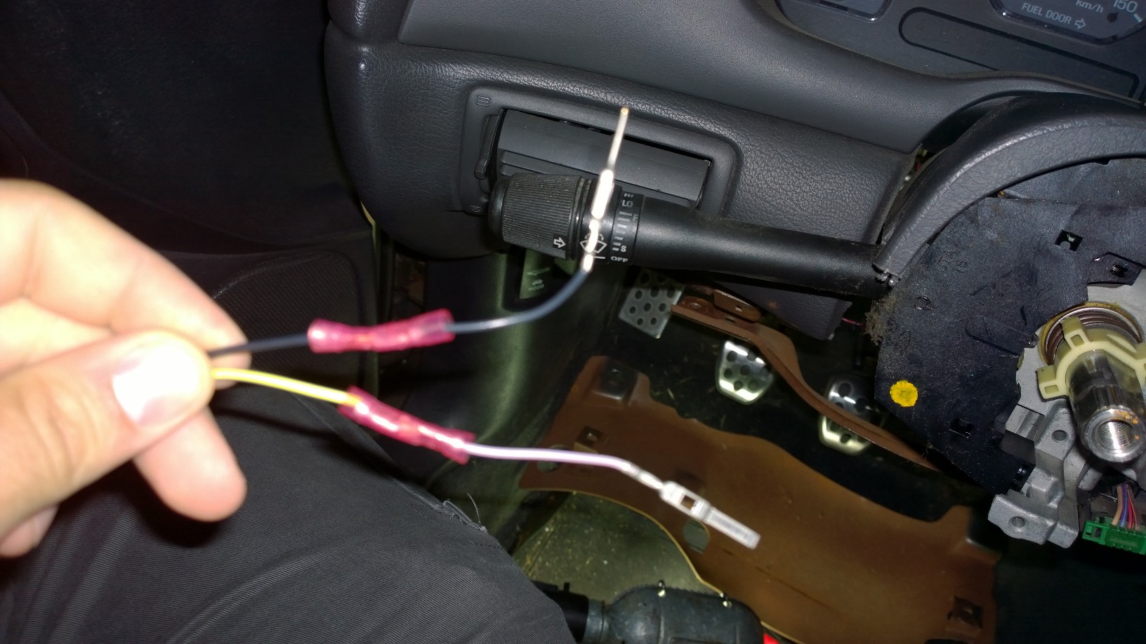
I then cut the purple and the black wire from the clock spring harness assembly and mated it to the horn contact switch end like so
I then followed my diagram of the connector before I disassembled it and reconnected the purple and black wire to the light grey female connector.
Please excuse my sasquatch
Now to deal with airbag issue I followed CliffyK's advice found here http://www.moddedmustangs.com/forum...rket-steering-wheel-have-srs.html#post5057342 which worked like a charm. I could not find a 2.3Ohm resistor anywhere so I got these E-Projects - 4.7 Ohm Resistors - 1/4 Watt - 5% - 4R7 (100 Pieces): Single Resistors: Amazon.com: Industrial & Scientific and when put in parralel the two 4.7 Ohm resistos become 2.35Ohms which works out.
I then wrapped the connector in electrical tape and called it a day, you could also use shrink tube.
Now to the steering wheel horn wiring.
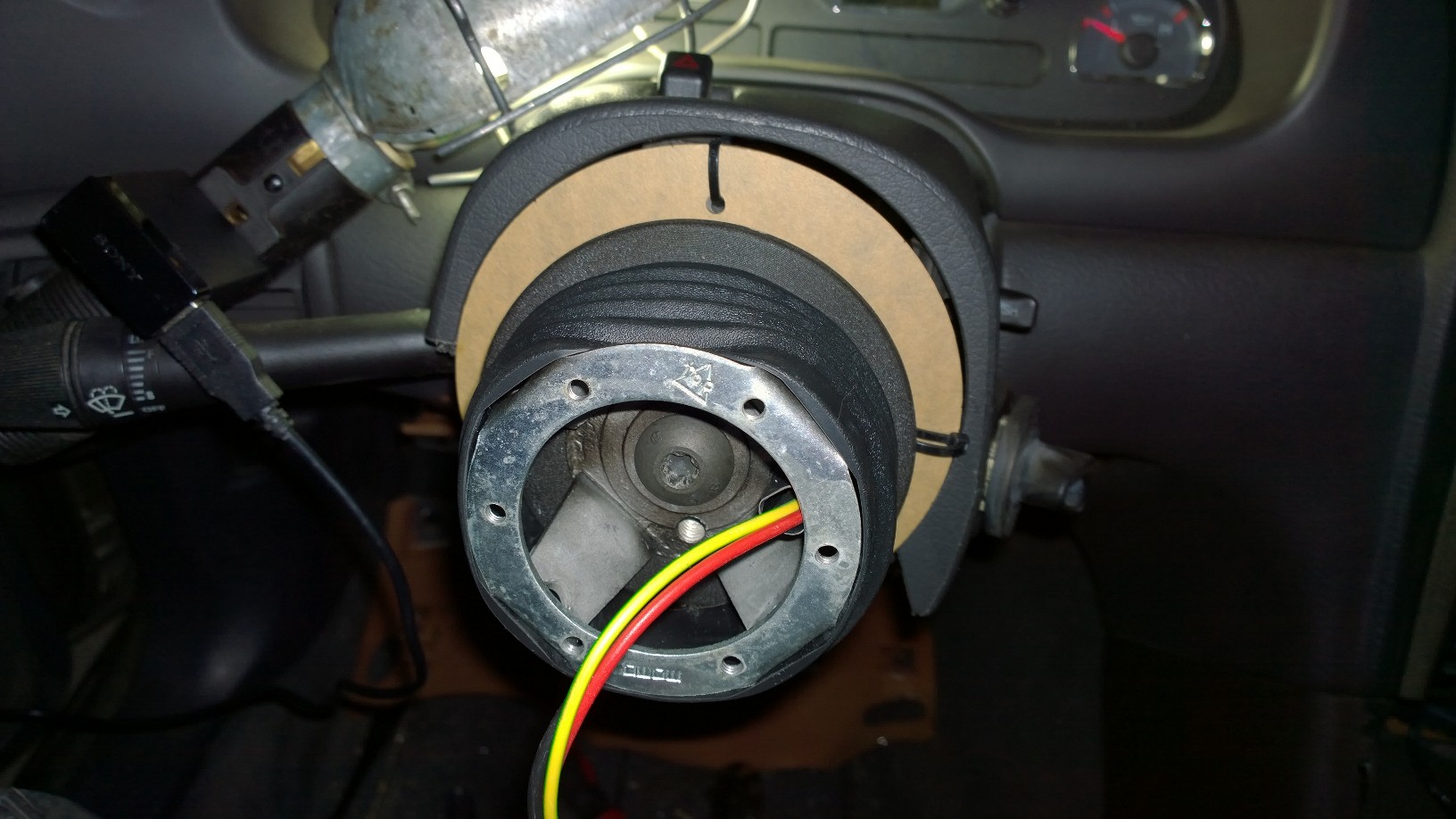
The steering wheel comes with a single green and yellow wire with two female spade connectors on each end, I cut this wire in half and crimped on some ring terminals and massaged them to make connection the plug coming out of the hub. This is not the ideal way of doing this but its just what I had to temporarily get this thing hooked up. I believe I have the mating side connector at work so I may just fix it. A side note if using the ford OEM horn contact switch the spring loaded pins will only make contact with the outside rings on the back of the hub, so the red and black wires will be the only ones used here.
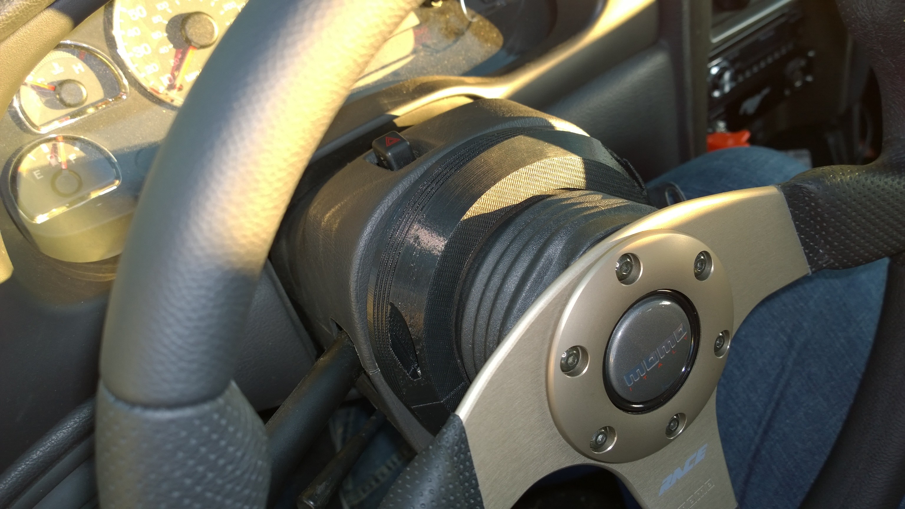
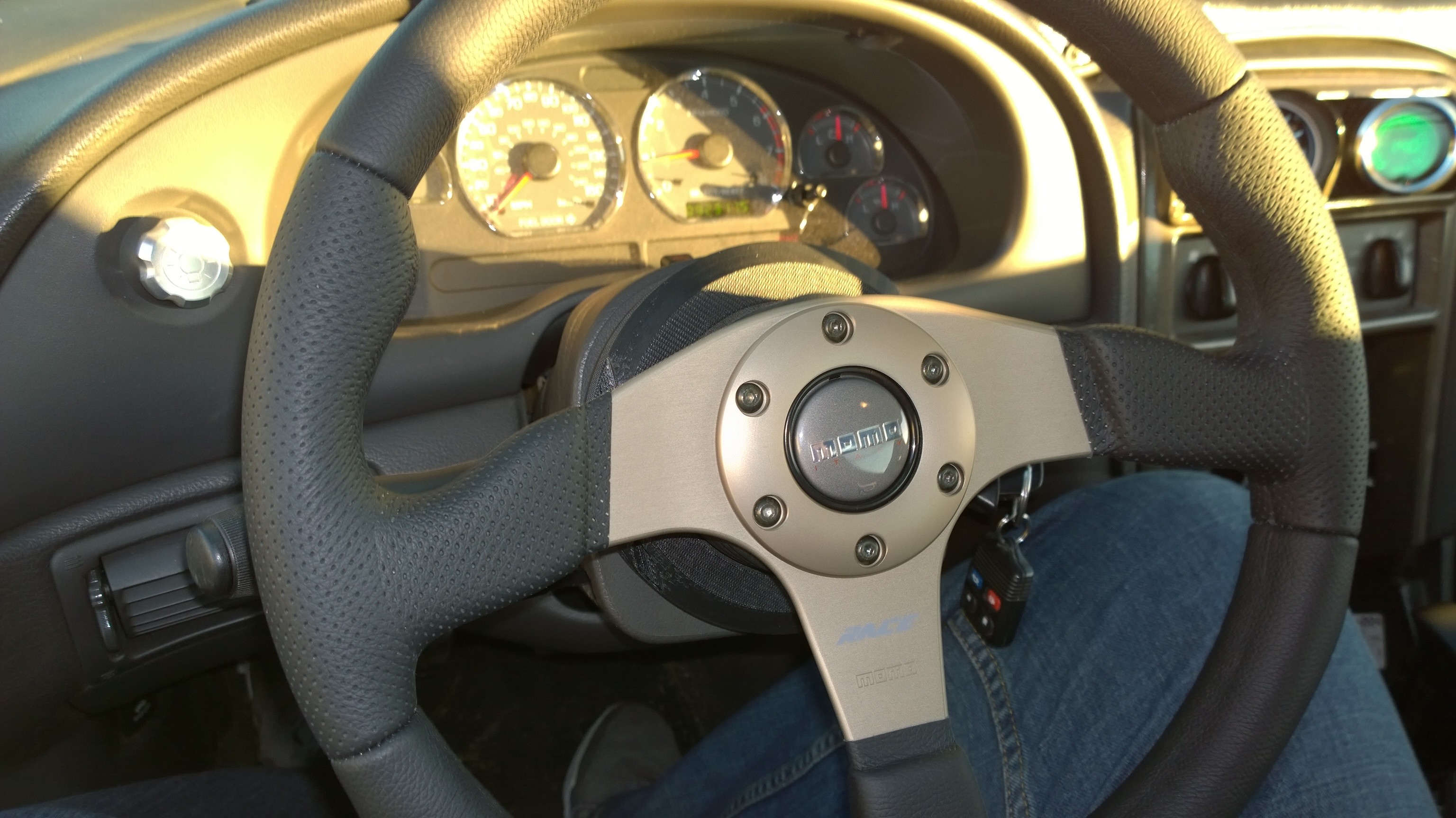
Slap it all back together and here is the finished product
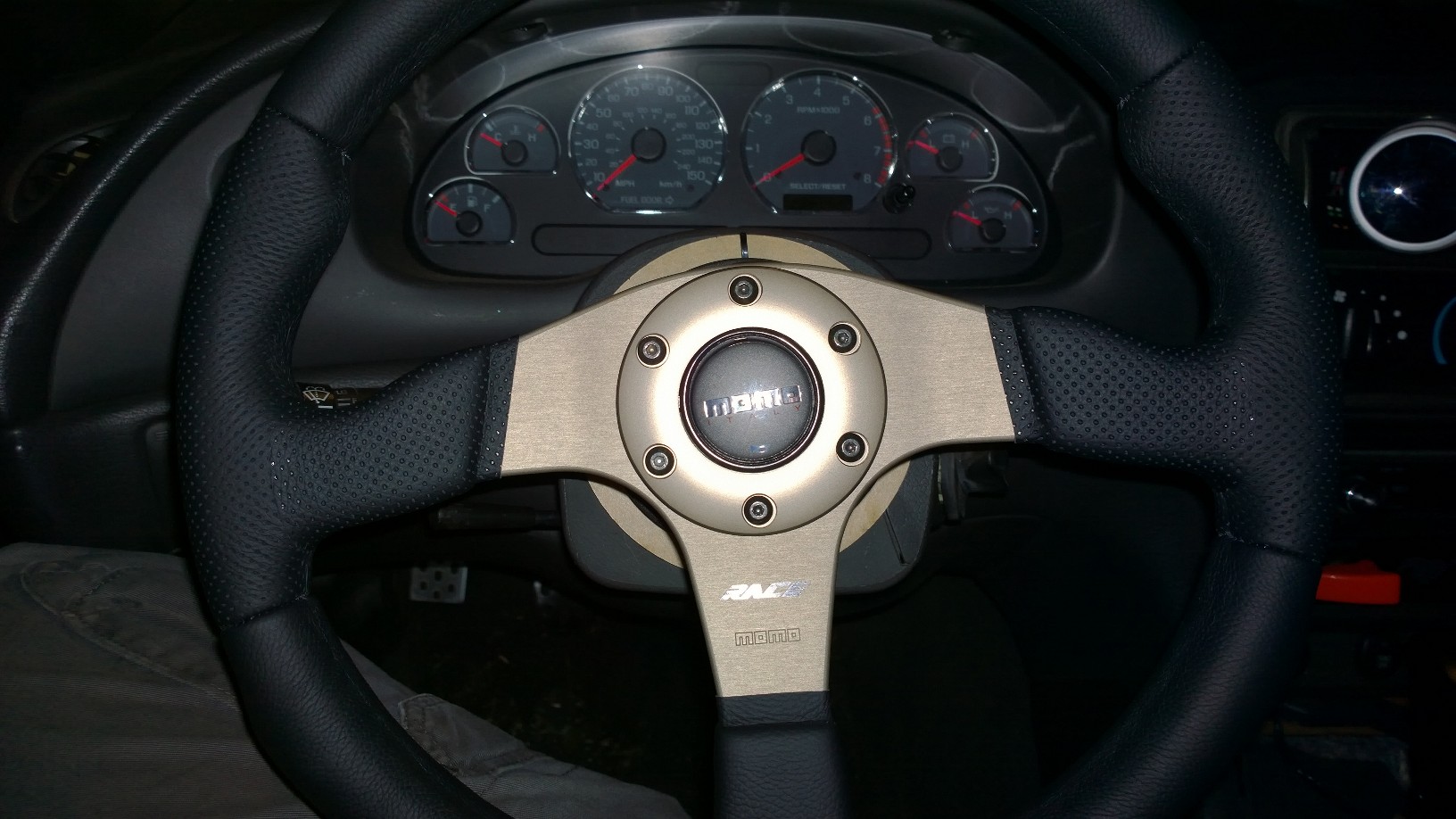
The steering feels awesome its just leaps and bounds better than the stock wheel so far Im pretty satisfied.
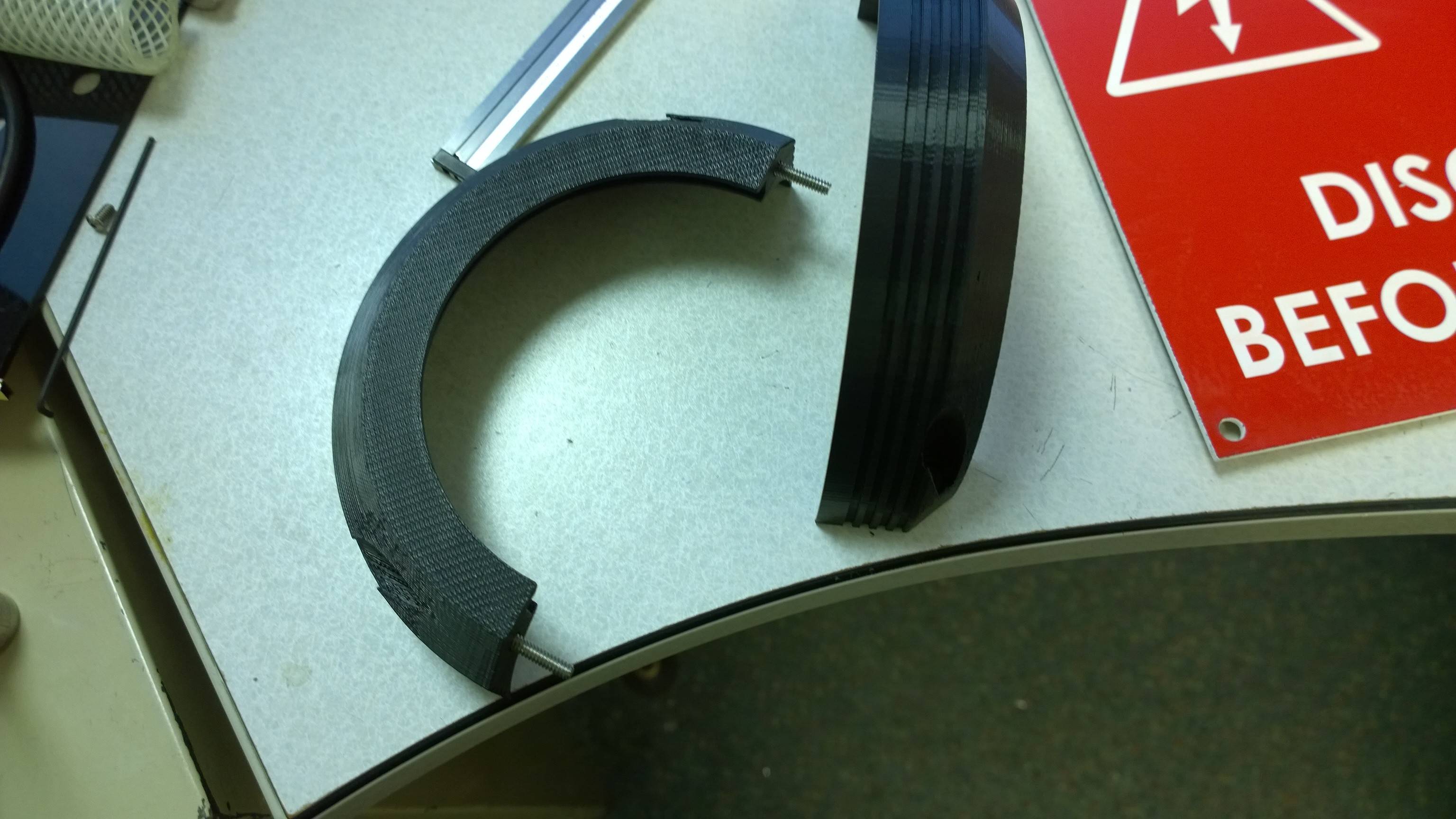
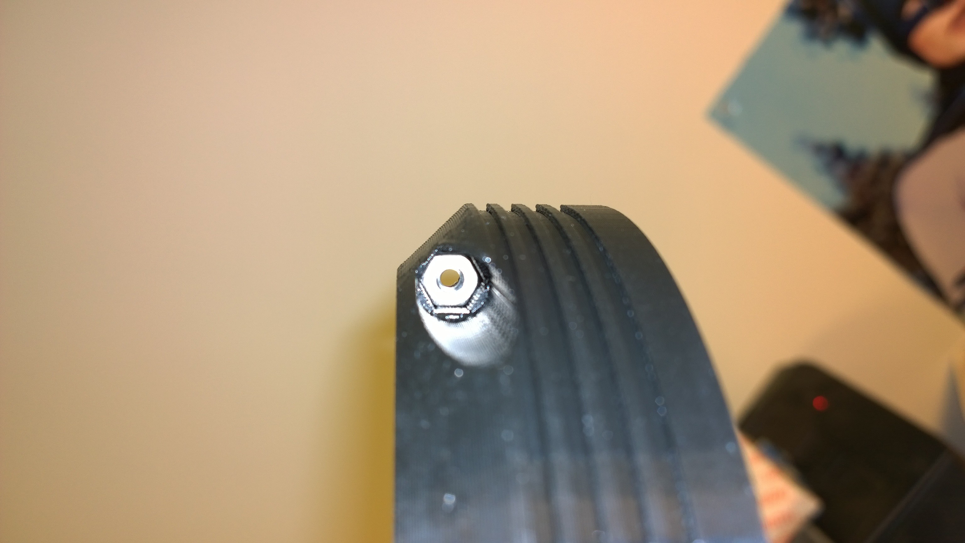
Still not finished, notice how the backside of the hub exposes the inside of the steering column and the sweet bracket I made. I also have access to a 3D printer so I went ahead and made a clam shell that just sits over the hole thing and hides it.
Here's the finished product
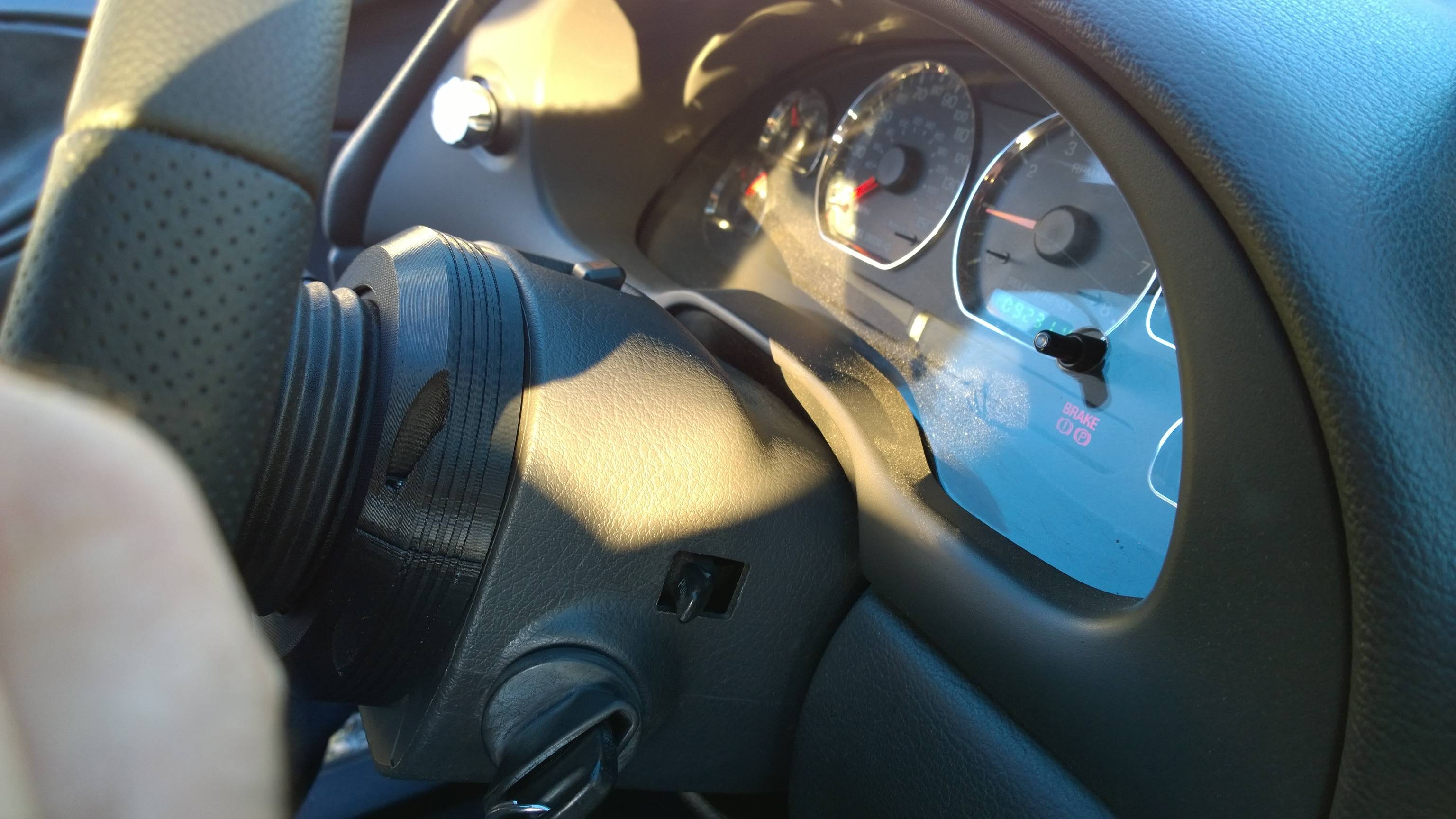
Hopefully this helps someone out there, I'm going to redesign the back clamshell so its prettier but it'll do for now.
So after much digging on the net and calling vendors I could not find a good DIY MOMO steering wheel and hub installation so I took matters into my own hands. So Here's what I purchased
http://www.americanmuscle.com/momo-race-steering-wheel.html
http://www.americanmuscle.com/steering-wheel-hub-8404.html
http://www.americanmuscle.com/ford-horn-contact-switch.html
My main concern was how to hook up the ford horn contact switch properly, and with zero info on it anywhere, or at least that I could find I went to work.
First things first, to do this install you'll have to remove the battery connections and let the car sit for at least 1/2hour because you'll be working with the air bag system and the last thing you want is that thing to go off in your face. Once the cables were free from the battery I took both battery cables and tied the terminals together with a bolt and nut to quickly dissipate the air bag capacitor's charge. When you shut your car off the airbag system has a capacitor which holds a charge for some period of time and keeps the airbag system energized until it drains out.
Next you'll need to remove the plastic knee panel and the metal knee panel under the steering wheel, they both have two bolts holding them in place, the plastic one however has some clips up top as well, should come off real easy.
you can follow these instructions here for removing the steering wheel FR500 Mustang Steering Wheel Installation Guide | AmericanMuscle
I also used this video to get to the clockspring assembly https://www.youtube.com/watch?v=0GUIZuIVxxU
I did this part a little differently from the video. I didn't remove the key tumbler I kept all of that in place including the PATS box/connector. I undid the air bag connector (brown) and the horn/cruise control connector (light grey)
If you watch the video he points out where all the clock springs clips are for removal which can easily be removed with the top half of the steering column in place. Another thing he mentions is that there are 3 screws holding the two column halves together but in our cars there is 4. Another thing I did differently is I took all the pins out of the connectors coming off the clock spring assembly going into the main harness. The reason for this was to be able to draw the wires through the opening under the key tumbler without worrying about the connectors getting caught on the backside, if you don't remove the pins from the connector you wont be able to pull the harness through the opening.
You'll need a small flat blade screw driver, looking at the light grey connector if you look inside you can see little tabs that can be bent. While holding the wire to be removed and pulling on it simultaneously, use the screw driver to free it. The airbag connector is a little different, first you have to remove the red safety clip inside the connector, this can be done by flipping to the backside of the connector there is a little slot the screwdriver can fit in and push up on the red safety tab causing it to come out where the pins are. The pin removal is than similar to the other connector.
Once that's done you can pull all the wires through the opening. There is one wire left that's keeping the hole assembly still attached and that's the black wire with a pink stripe going to the key tumbler, this wire controls the door chime when you have the key in the ignition. You can either disassemble the tumbler and its corresponding components to remove it intact or just cut it, which is what I did.
Once the clock spring assembly was removed I noticed there were three holes located on the steering column. I took some measurements of the hole locations with respect to the steering shaft and sketched up a bracket. I have access to a cnc laser cutter so I cut mine out of 1/8" acrylic. I measured the two prong horn switch connector and mounted it to the bracket utilizing its two pins and hole to fasten it to the plate I just cut out. 1/8" is probably the thickest you want to make it other wise the the prongs will bottom out and you could potentially have the connector housing rubbing on the MOMO hub's slip rings. Heres is a dimension drawing https://www.scribd.com/doc/284213720/Mounting-Plate it should be 1:1 so you can print it and use it as a template or just use the dimension, its on an 11 x 17 paper format . I forgot to take a picture of the just the connector and the bracket installed. Don't mind the zip ties I didn't have the right size screws laying around but here's the finished product.
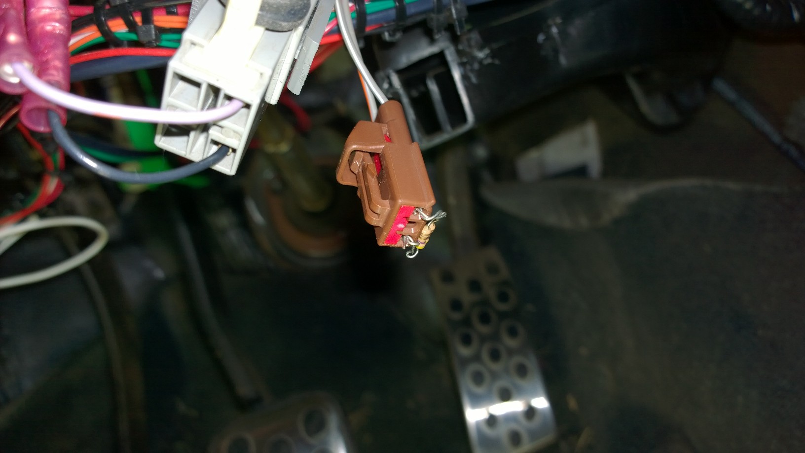
I then cut the purple and the black wire from the clock spring harness assembly and mated it to the horn contact switch end like so
I then followed my diagram of the connector before I disassembled it and reconnected the purple and black wire to the light grey female connector.
Please excuse my sasquatch
Now to deal with airbag issue I followed CliffyK's advice found here http://www.moddedmustangs.com/forum...rket-steering-wheel-have-srs.html#post5057342 which worked like a charm. I could not find a 2.3Ohm resistor anywhere so I got these E-Projects - 4.7 Ohm Resistors - 1/4 Watt - 5% - 4R7 (100 Pieces): Single Resistors: Amazon.com: Industrial & Scientific and when put in parralel the two 4.7 Ohm resistos become 2.35Ohms which works out.
I then wrapped the connector in electrical tape and called it a day, you could also use shrink tube.
Now to the steering wheel horn wiring.
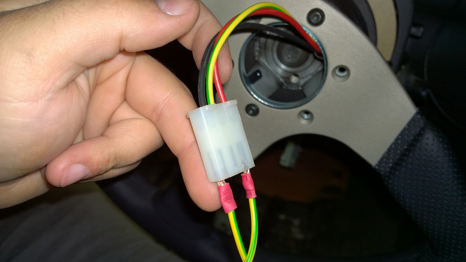
The steering wheel comes with a single green and yellow wire with two female spade connectors on each end, I cut this wire in half and crimped on some ring terminals and massaged them to make connection the plug coming out of the hub. This is not the ideal way of doing this but its just what I had to temporarily get this thing hooked up. I believe I have the mating side connector at work so I may just fix it. A side note if using the ford OEM horn contact switch the spring loaded pins will only make contact with the outside rings on the back of the hub, so the red and black wires will be the only ones used here.
Slap it all back together and here is the finished product
The steering feels awesome its just leaps and bounds better than the stock wheel so far Im pretty satisfied.
Still not finished, notice how the backside of the hub exposes the inside of the steering column and the sweet bracket I made. I also have access to a 3D printer so I went ahead and made a clam shell that just sits over the hole thing and hides it.
Here's the finished product
Hopefully this helps someone out there, I'm going to redesign the back clamshell so its prettier but it'll do for now.