Well, this build has been going since November 2007 but the old thread was lost when we switched hosts. I'm going to do my best to re-host all the pictures and get this very long thread back up a piece at a time. Bear with me.
________________________________________________________________________________
Here's my thread for the build of my small block Ford 306 engine for my 1989 Mustang coupe. It is a budget build with relatively simple and not-that-expensive parts in it. This is the first time I've built an engine completely from scratch, so I'm excited to do and I'm sure I will learn a lot along the way. This build has been going since December, and the first post should put everyone up-to-date.
The bottom-half components are as follows:
Production 5.0 (302) block, borded .030", align honed
OEM Crank, ground .010, polished, oil holes chamfered, balanced rotating assembly
Probe forged I-beam rods
Probe forged pistons, 4.030"
Clevite 77 main and rod bearings
Sealed Power gapless moly piston rings, 4.030"
ARP main and head studs
ARP harmonic balancer bolt
OEM harmonic balancer, 50 oz imbalance
Centerforce Billet Steel flywheel, 50 oz imbalance
Double roller timing chain
Trick Flow Stage 1 camshaft (.499"/.510" lift, 221/225 degrees duration @ .050" lift, 112* Lobe Separation Angle)
The top end consists of:
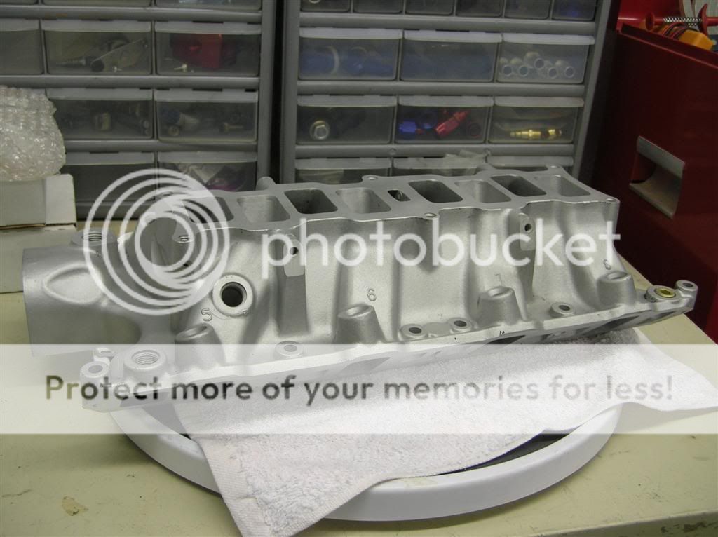
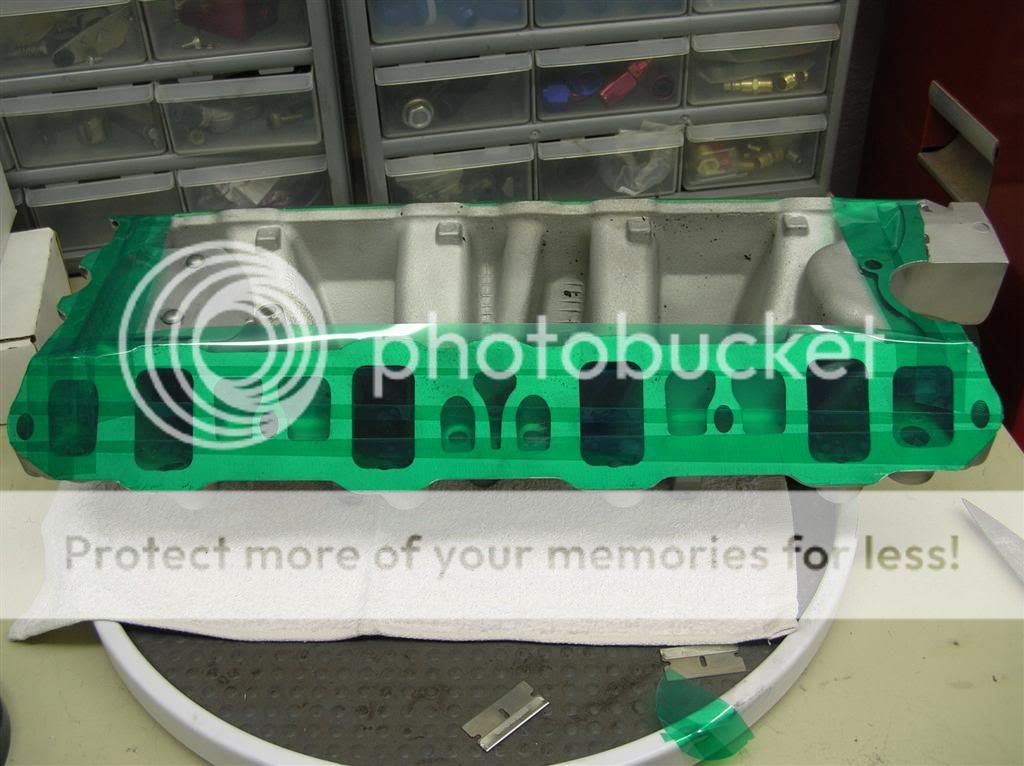
TFS Street Heat Intake
TFS Twisted Wedge Heads
TFS 1.6 Roller Rockers
Accufab 70mm Throttle Body and EGR Delete
FRPP Stainless Shorty Headers
Well, I stayed up late last night mocking up the entire rotating assembly with a buddy of mine and checking tolerances on the main and rod caps with plastigage. I also checked crankshaft endplay. My tolerances so far are as follows:
Main cap oil clearances:
Cap 1: .0015"
Cap 2: .0015"
Cap 3: .0015"
Cap 4: .0015"
Cap 5: .0015"
Crankshaft endplay:
.0038" (a little tight, spec is .004" - .008", but I will live with it. It should open up immediately upon startup and the first time I push the clutch)
Rod cap oil clearances:
#1 - .0015"
#2 - .0015"
#3 - .0018"
#4 - .0018"
#5 - .0013"
#6 - .0015"
#7 - .0018"
#8 - .0013"
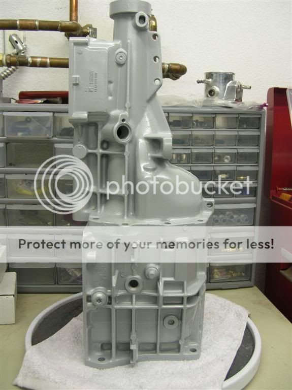
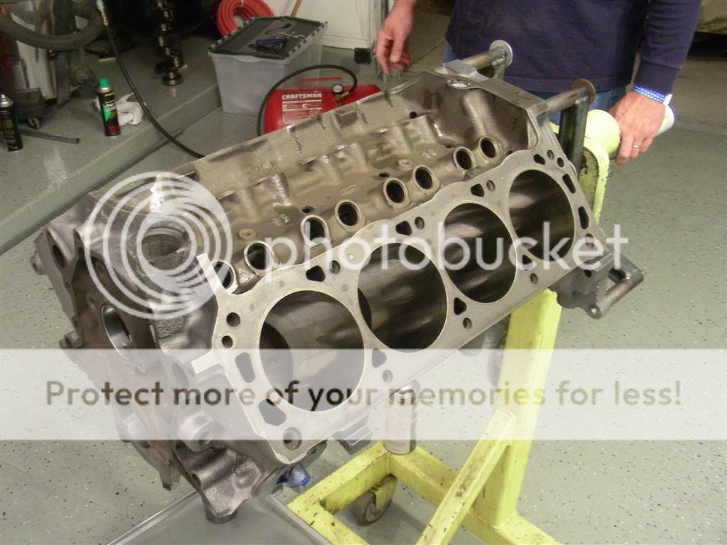
Here's the block after I masked it all off and painted it cast iron grey.
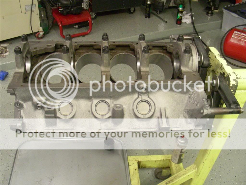
This motor had OEM main cap bolts, so I replaced them with these ARP main studs for a little extra strength.
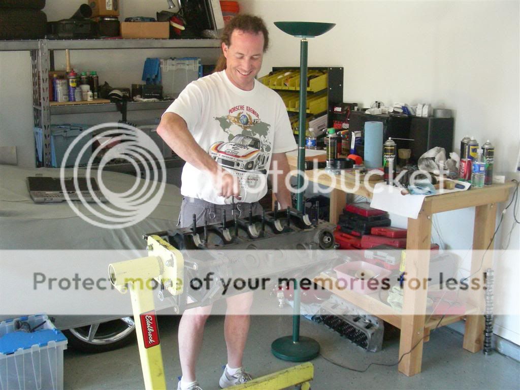
This is my friend Mike (he's a CNC machinist by trade) chasing threads on the block while I was cleaning the crankshaft out.
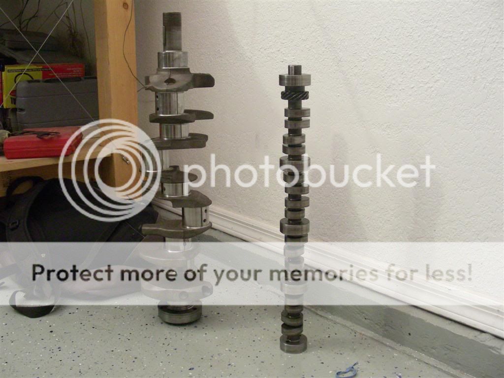
Here's the crankshaft (OEM) and Trick Flow Stage 1 cam.
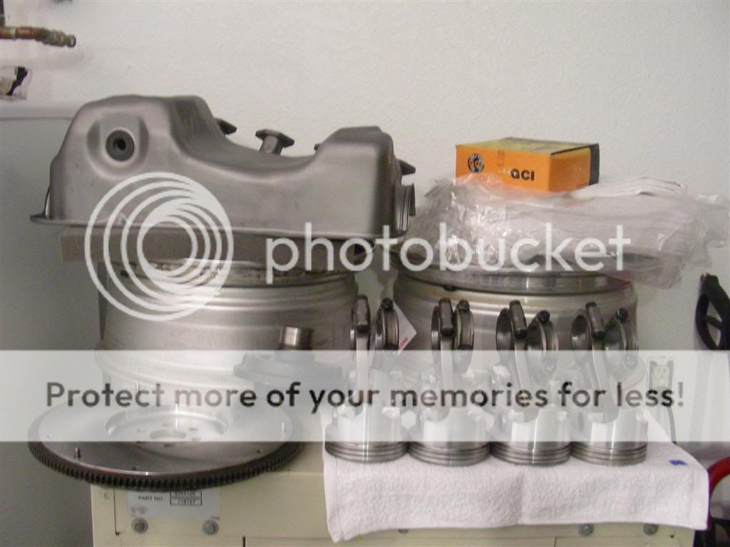
Here's the pistons, rods, flywheel, and balancer. In that picture you can also see my oil pan and headers that I blasted with steel shot. Those will get powdercoated later.
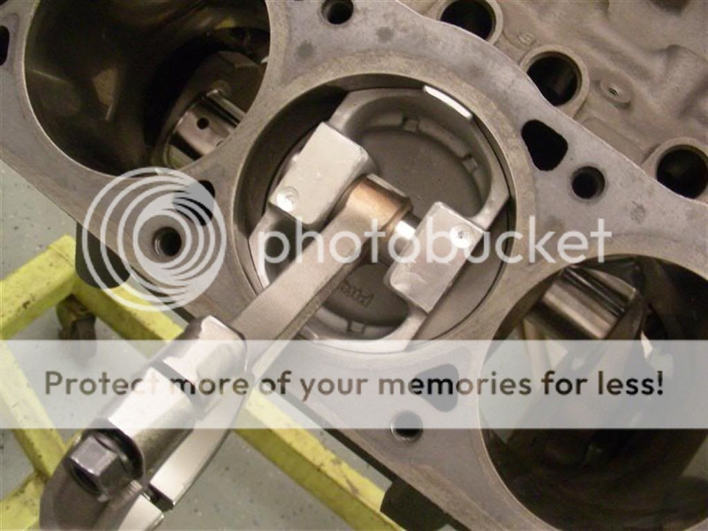
This is a picturing of the plastigage measurement on one of the main caps.
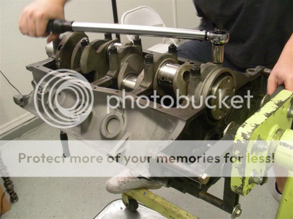
Here's me torquing down the main caps to 70 ft. lbs. for the last of many times.
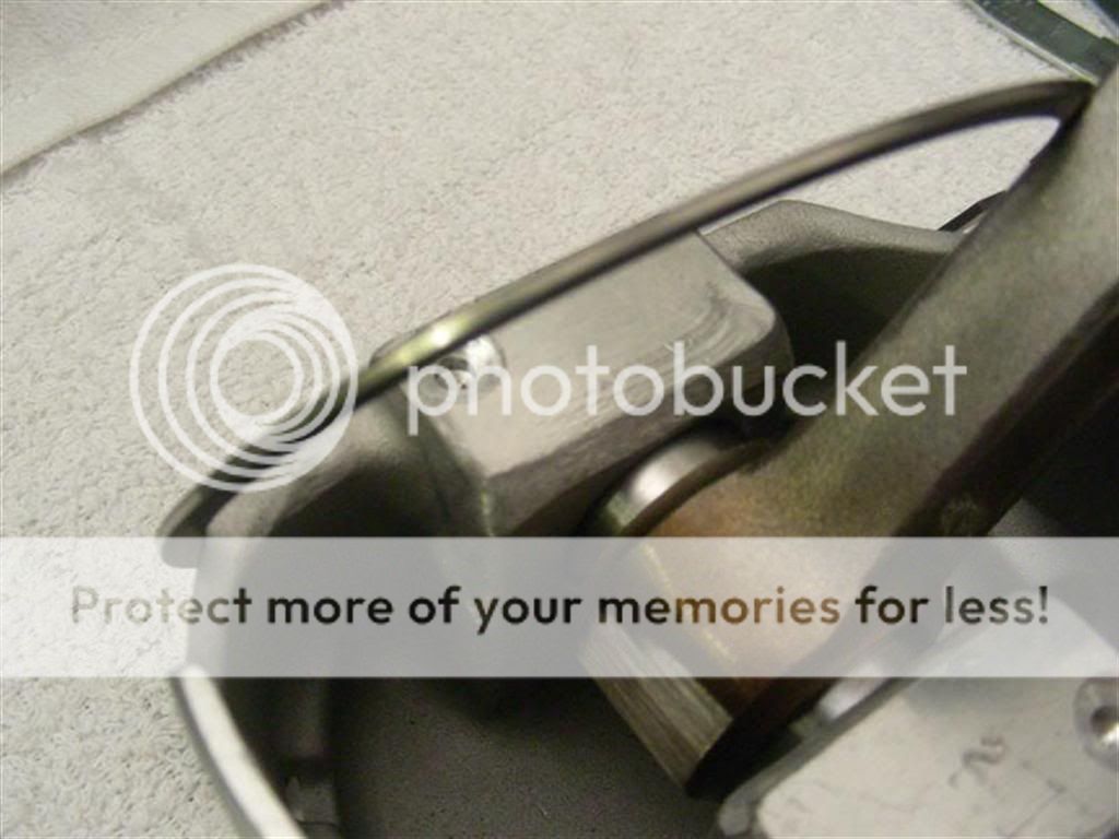
Here we are setting up the dial indicator to measure crankshaft endplay. When I did this the second time, I used my magnetic base instead of the clamp - it was easier.
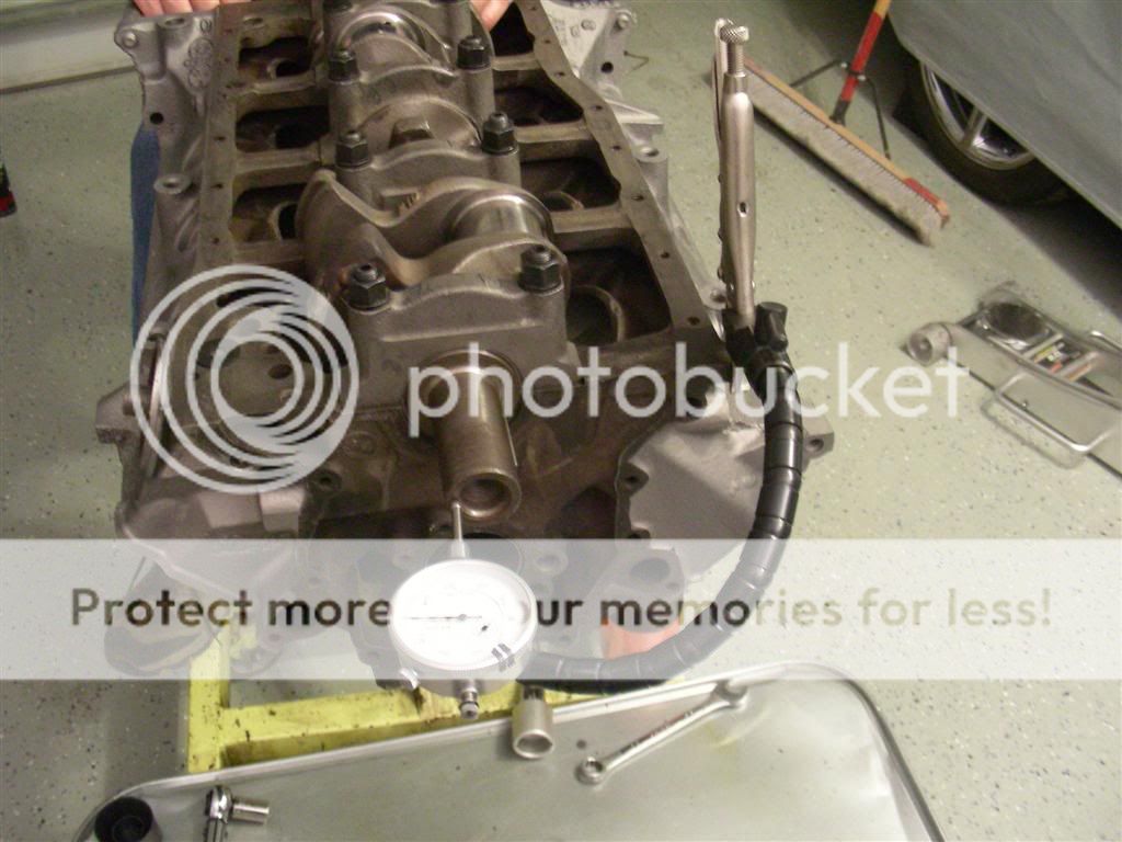
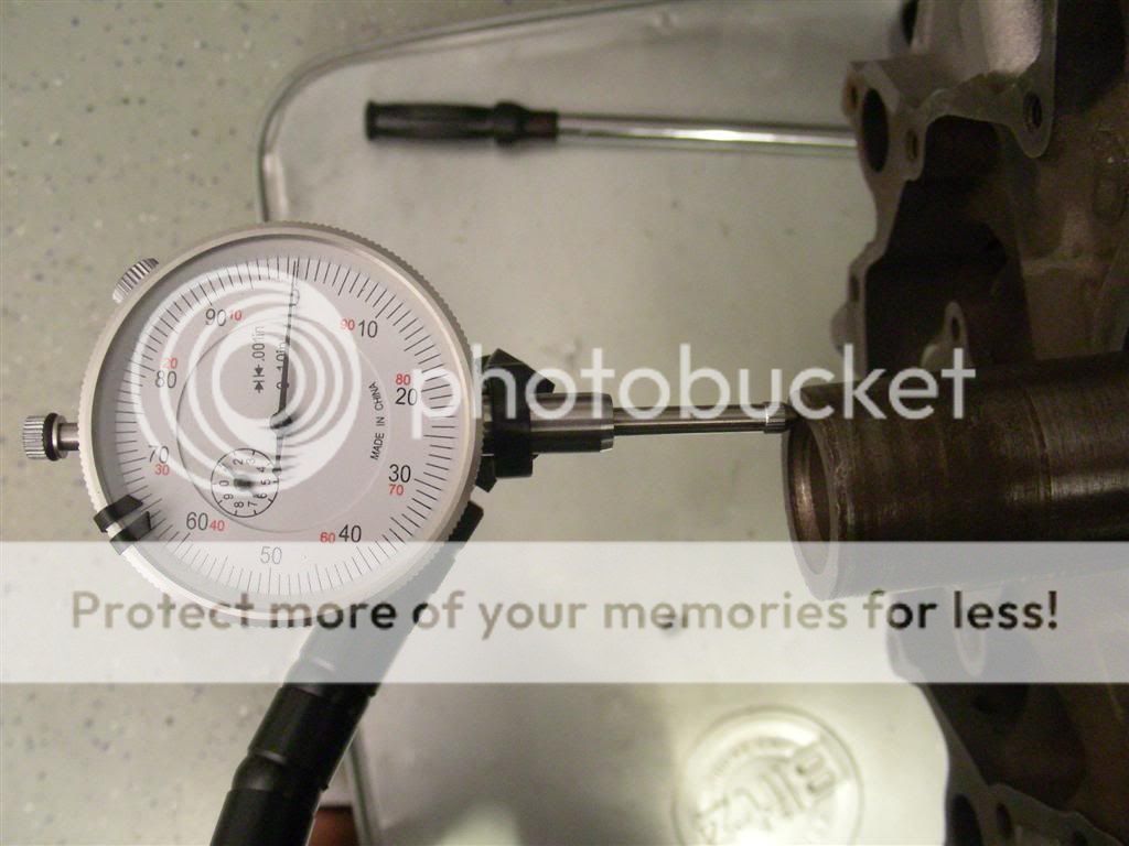
To measure endplay, you set up the dial indicator, zero it, then move the crankshaft forward and backward with a prybar. Endplay should be .004" to .008" - the reason I took this motor apart was because endplay was .131" ... seriously. The crank moved so far forward when I pushed the clutch that the flywheel would actually hit the inspection plate on the bellhousing.
Next, I checked the ring gap, here's what I came up with:
Piston #1
Top Ring: .016"
Second Ring: .016"
Piston #2
Top Ring: .016"
Second Ring: .016"
Piston #3
Top Ring: .018"
Second Ring: .016"
Piston #4
Top Ring: .018"
Second Ring: .016"
Piston #5
Top Ring: .018"
Second Ring: .017"
Piston #6
Top Ring: .018"
Second Ring: .016"
Piston #7
Top Ring: .016"
Second Ring: .014" (was .016" down in the bore)
Piston #1
Top Ring: .020" (was .018" down in the bore)
Second Ring: .016"
So this is basically what I did:
First, remember these important words of wisdom... For safer engines, always use a condom.
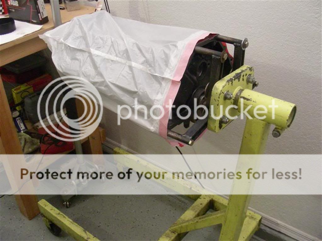
And since I'm a bit paranoid, I always double bag it.
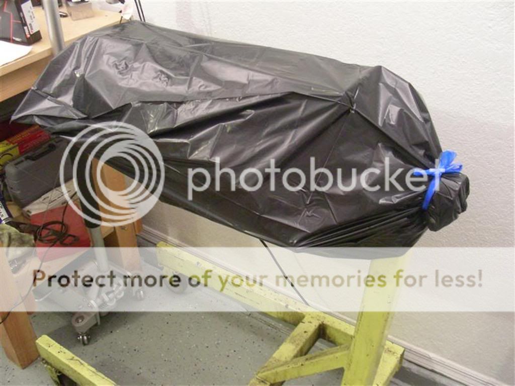
The first thing you need to do if you want to make this easy on yourself is buy a piston ring installer. This little tool makes it really easy to pop the rings in the grooves without scratching the crap out of the side of your ring lands. I picked this one up from Pep Boys for six bucks.
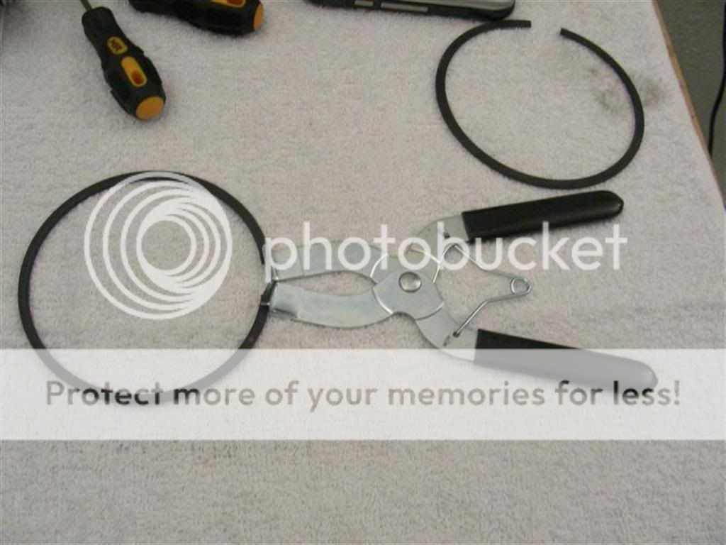
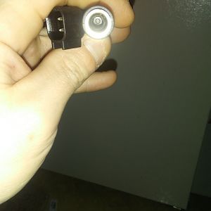
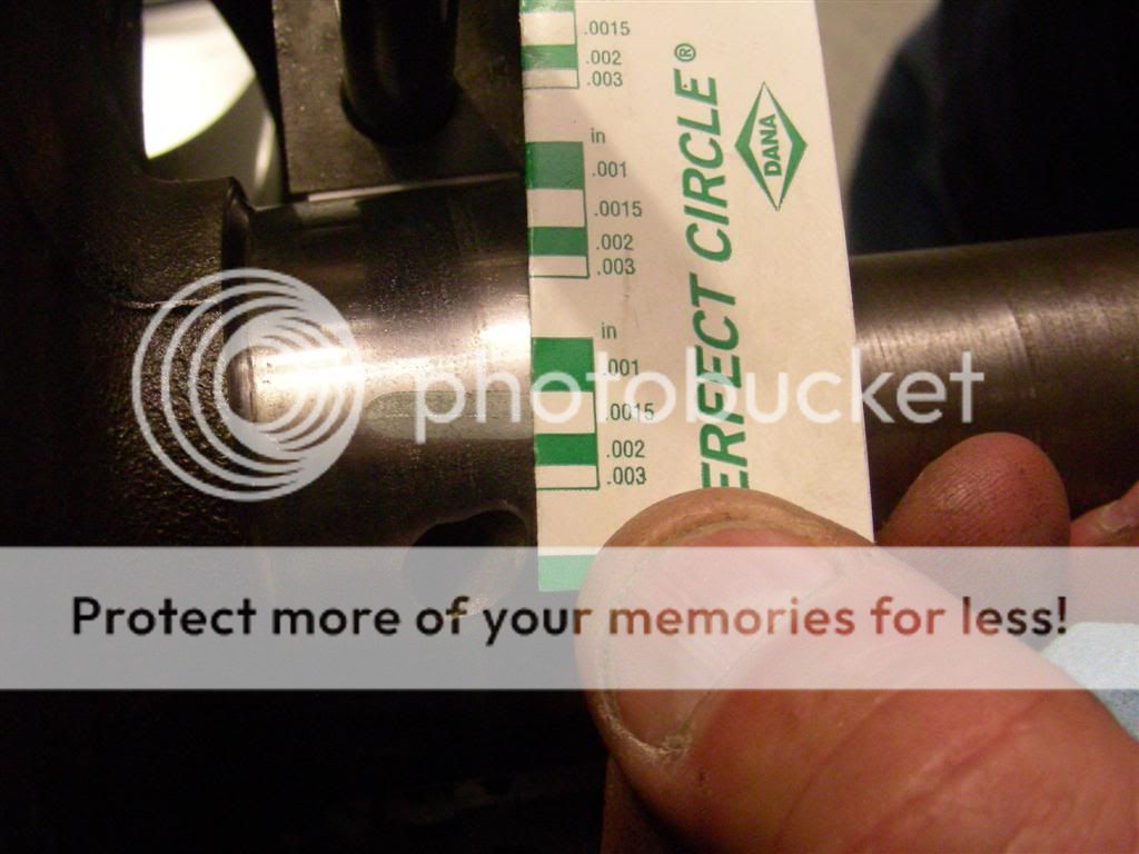
Then you need to figure out which rings go where, and how they're oriented. The ones with the shiny edge are going to be your top ones. Here is a crummy picture of the edge of my top ring.
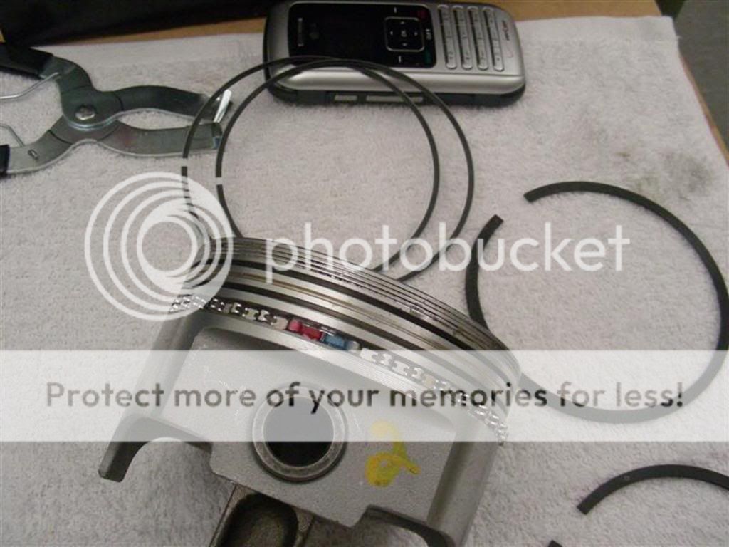
Next, you have to keep in mind that there is an "up" and "down" side of the ring. You'll notice in this picture below that there's a tiny white circle on the ring. That circle means "this side up." On the second ring it's not as easy to see. Mine looked like a dent more than a dot.

Once you got that figured out, you can measure ring gap. This is actually really easy. All you need is a set of feeler gauges and one of your pistons. First, squeeze the ring into the bore. Be careful to not scratch the hell out of your bores with any sharp edges.
Then, take your feeler gauges and see what the largest one that you can squeeze in the gap is.
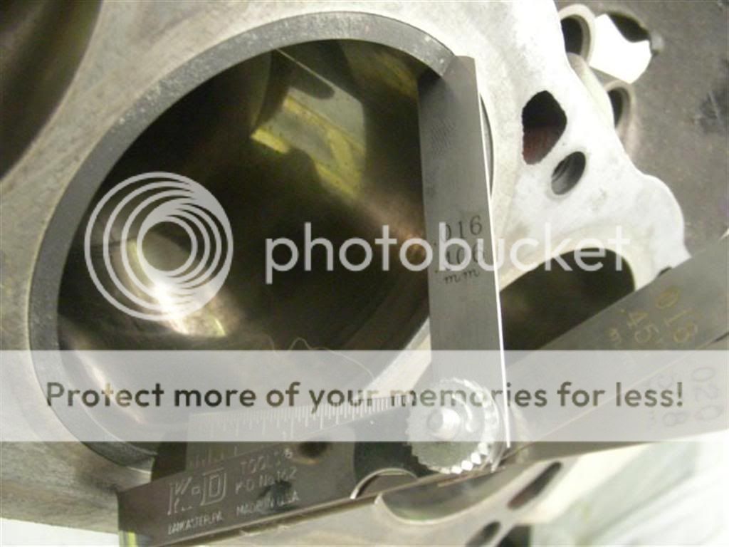
Then, using your piston to square up the ring to the bore, push the ring down a couple inches into the bore so you can take another measurement with your feeler gauges.
If you're satisfied with your ring gap, then you can install them on the pistons. Make sure to install the rings "180 apart", meaning that if the gap is on one side of the piston for the top ring, put the gap for the second ring on the other side. Also, when installing your oil rings, make sure that the ends are butted up against eachother, not overlapped. My rings came with painted ends to help you make sure they're seated appropriately.
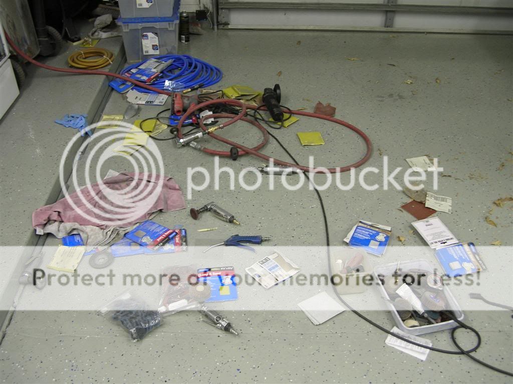
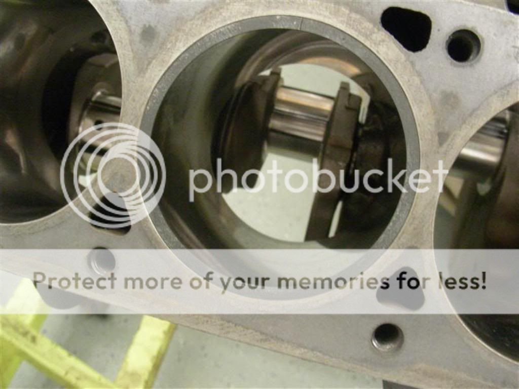
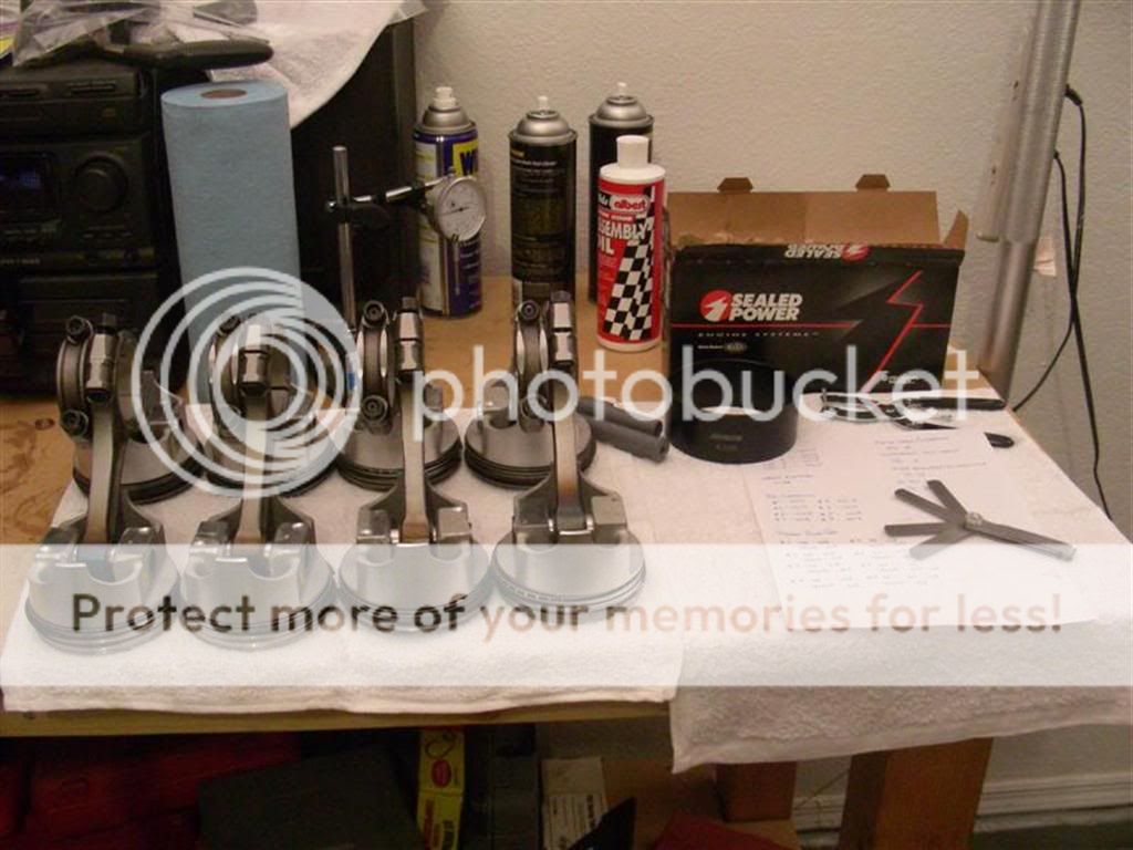
So, that's really all there is to it. In the next installment, I'll post some pics of installing the pistons in the block. This is pretty simple though, you just need a ring compressor and a plastic hammer. You can see my one-piece 4.030" ring compressor in this picture - it is quite a bit easier than the weird ratcheting ones you can rent at the parts store. So, with that - here's a picture of all of my pistons with the rings installed and the tools I needed to do it.
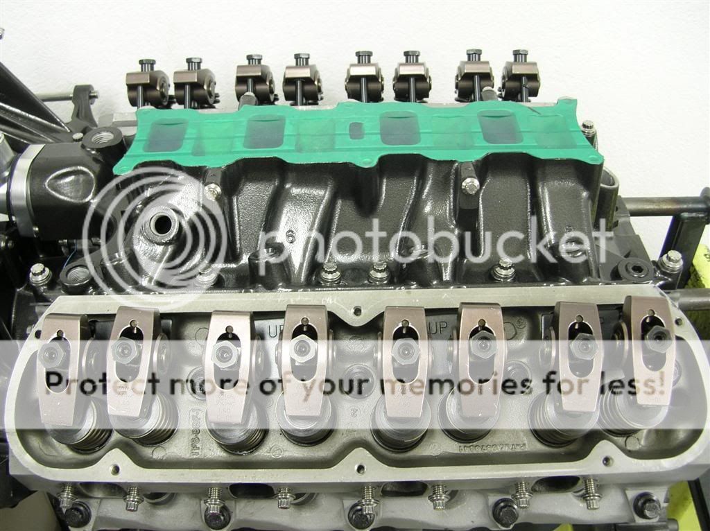
At this point, the entire longblock is built, the cam is degreed and installed, and the valvetrain is completely assembled. Sorry, I don't have pics of that part of the build.
Today, I began bolting up the timing cover up.
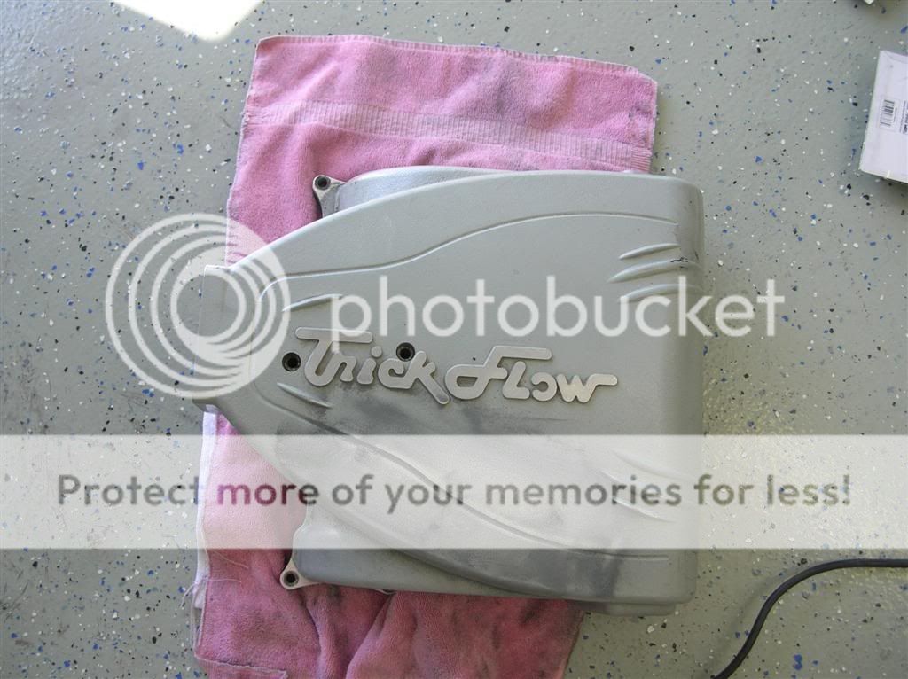
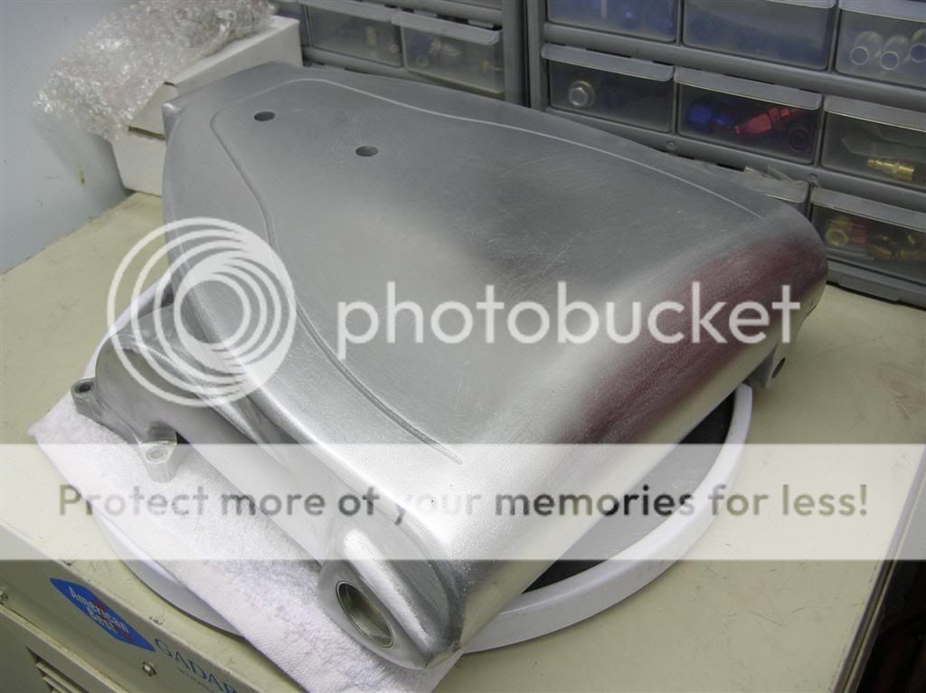
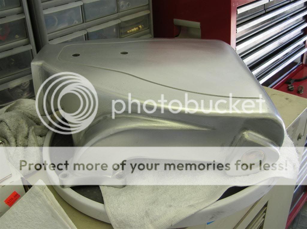
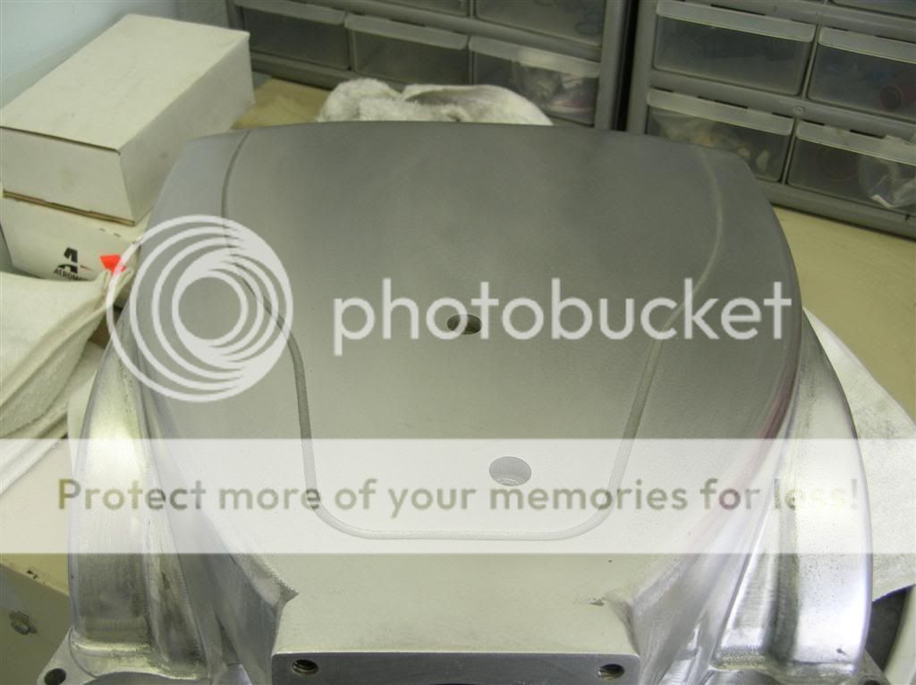
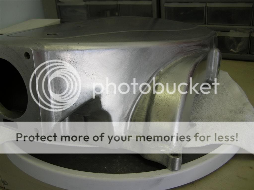
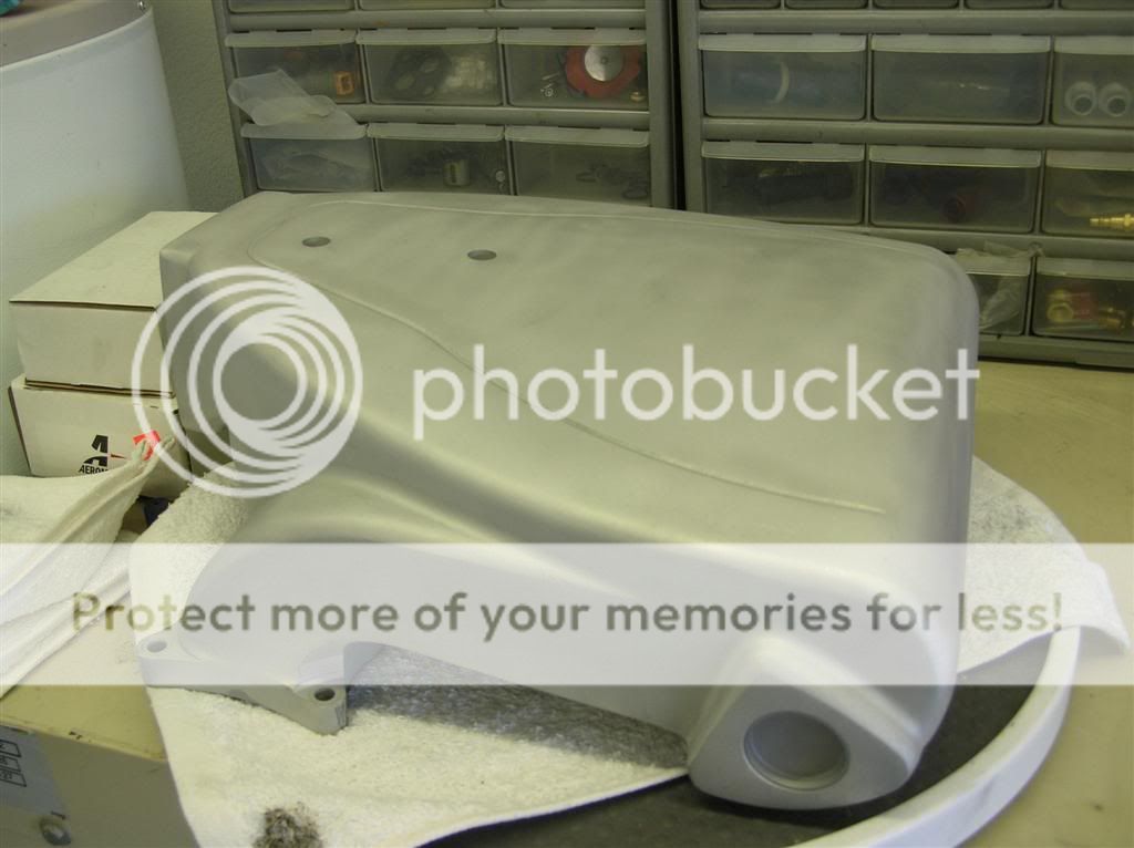
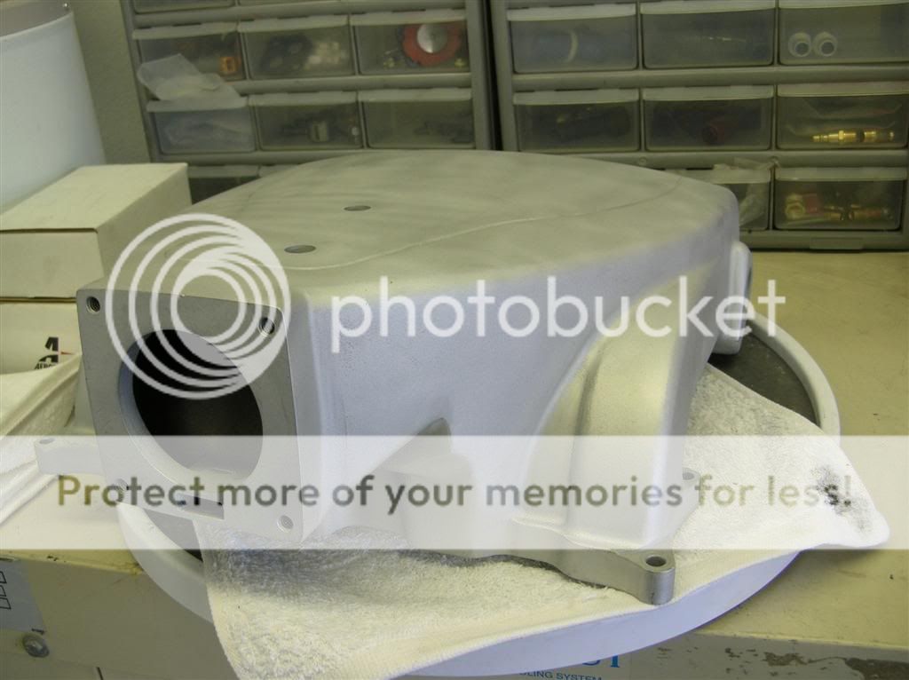
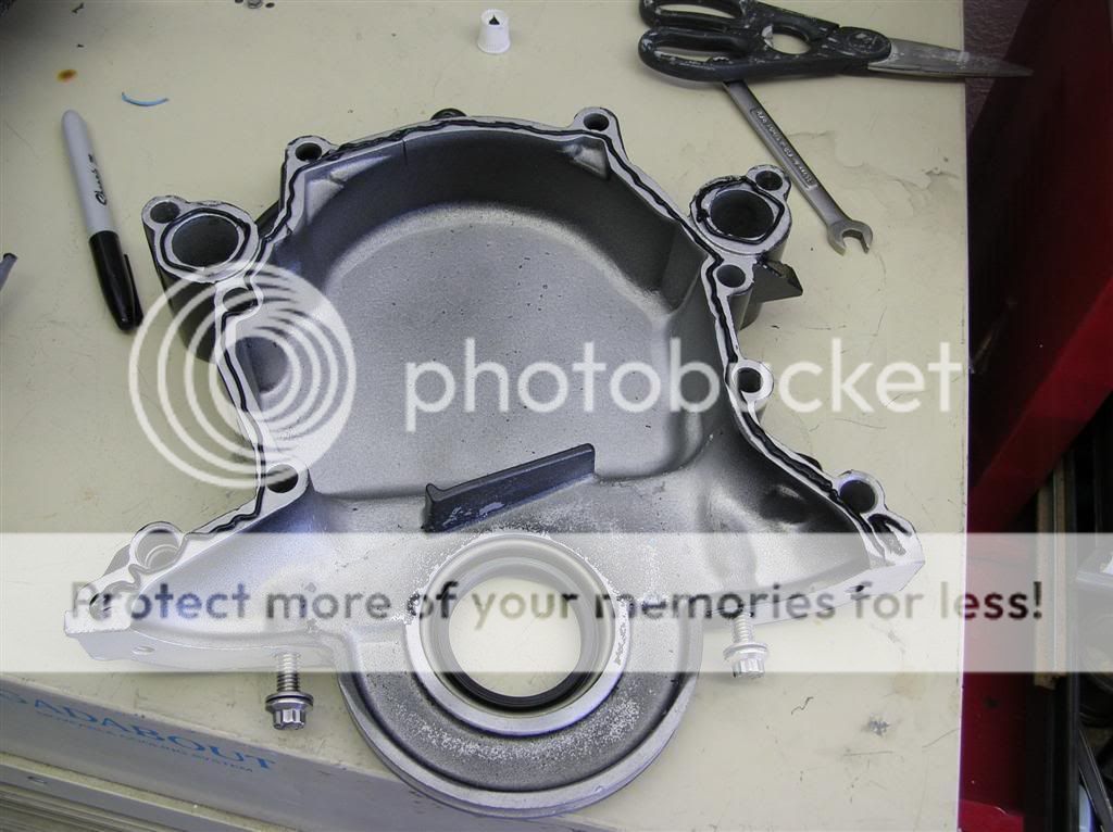
Here's my timing cover that I powdercoated.
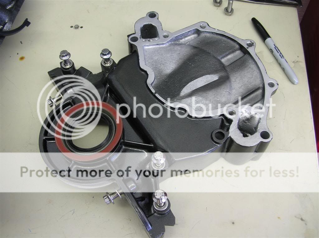
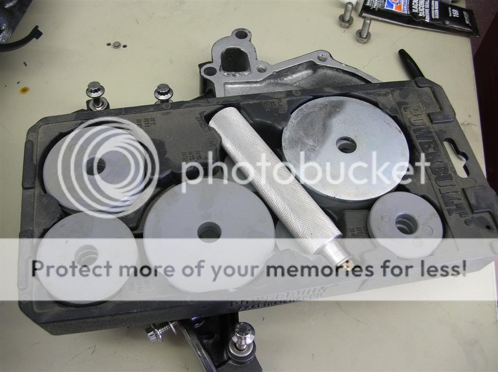
I used a seal installer to put the front seal in without messing it up.
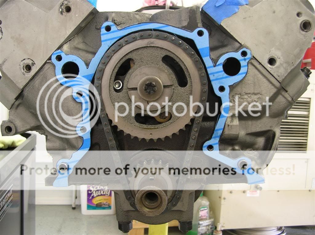
Then I carefully trimmed the timing cover gasket so it wouldn't show too much once it was installed, and applied a thin bead of RTV.
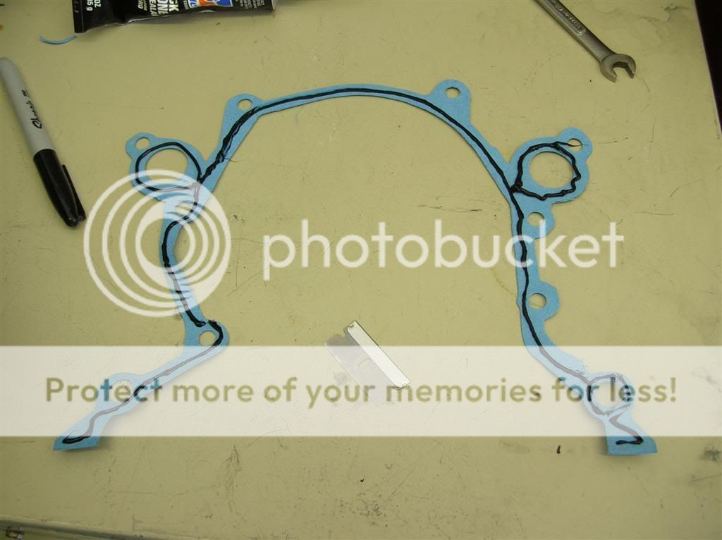
Once that had "set up" a bit, I installed it on the block.
Then I put another thin bead of RTV on the timing cover and installed it on the block.
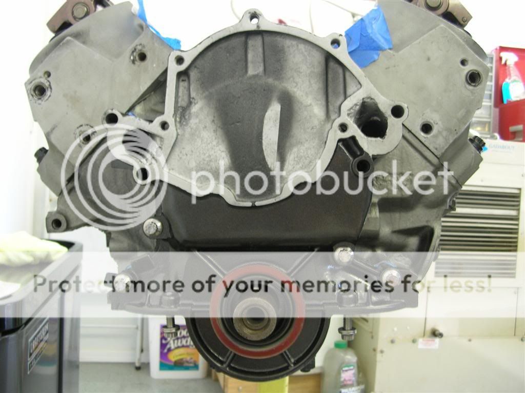
I also put some JB Weld in one coolant passage on the timing cover because it was pretty badly pitted.
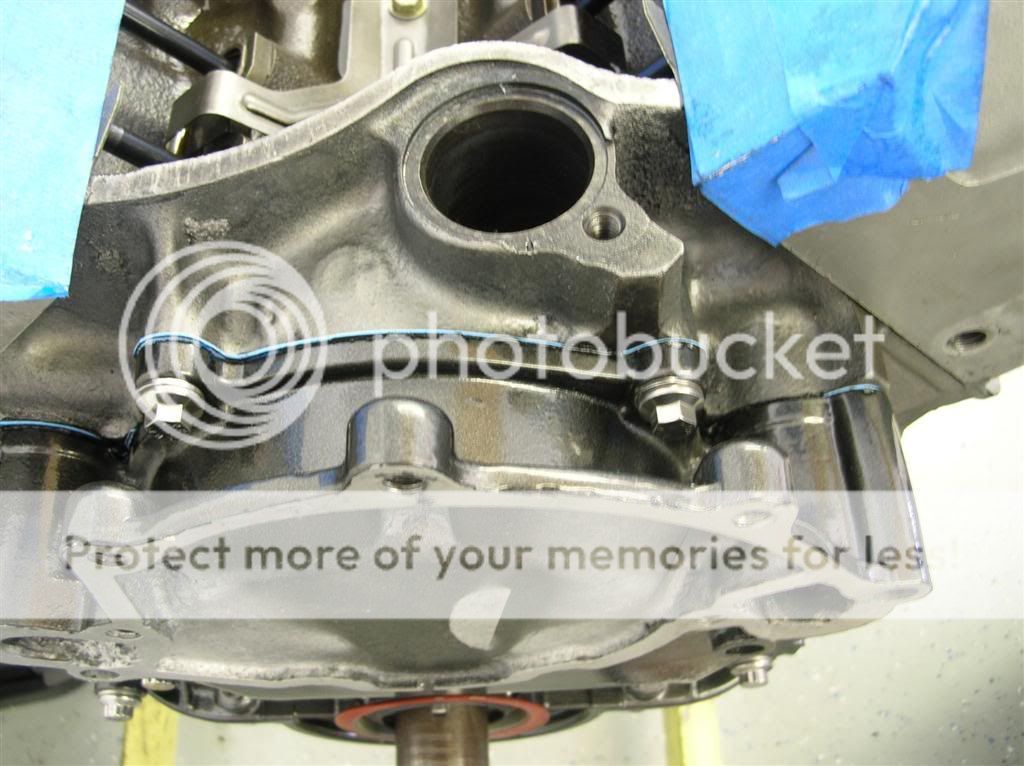
I put a thin bead of RTV on the water pump gasket, and squished it on the timing cover.
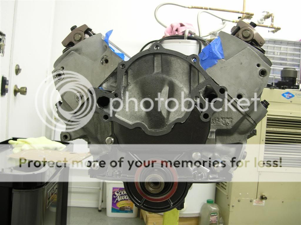
Then I attached the water pump. This thing is a behemoth - it weighs TEN POUNDS.
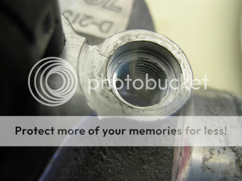
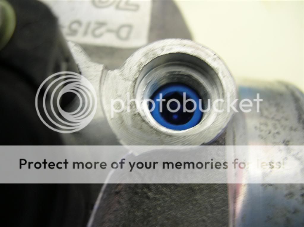
The stupid studs are ugly and a pain in the ass. I had to run a die over all the threads and a tap through the flange nuts to make them thread easily.
Anyway, then I flipped the motor over and installed the oil pump. Always remember to take cover off the oil pump, and inspect the gerotor and casting for any nicks or burrs. The last one I got had a huge nick in it and I returned it. Then I installed the oil pickup, and re-used my one-piece oil pan gasket. I hope this damn thing seals. I put a dab of RTV in the corners for good measure.

The I put the pan on - this was the one I powdercoated a while back in flat black. I love the way the finish turned out. I tightened down the bolts in two torque sequences, 9 and 15 ft. lbs., starting from the center and working my way out.
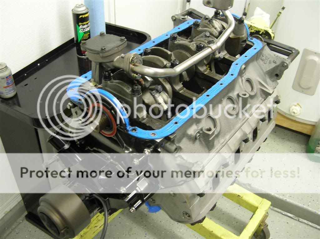
Later on I realized that I forgot to put anti-seize on ALL the oil pan bolts, so I have to take it back off and re-do it all over again. Dammit.
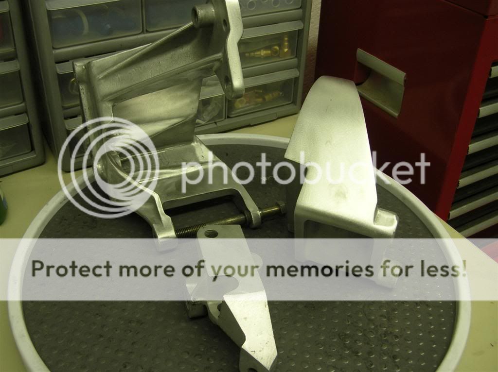
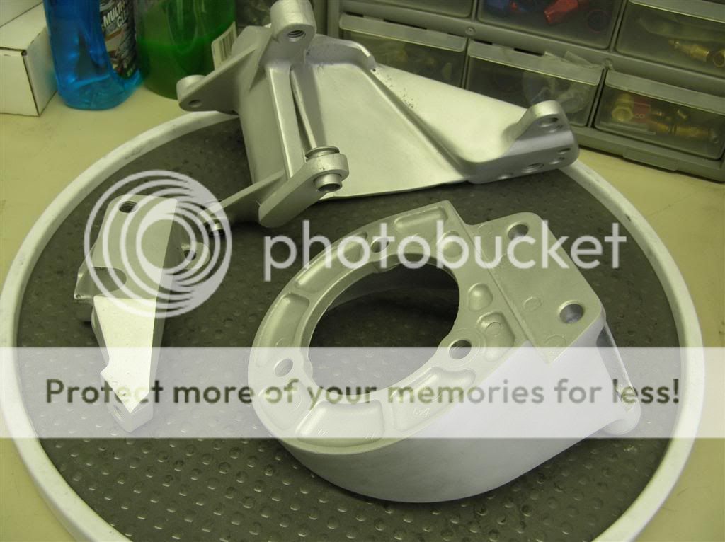
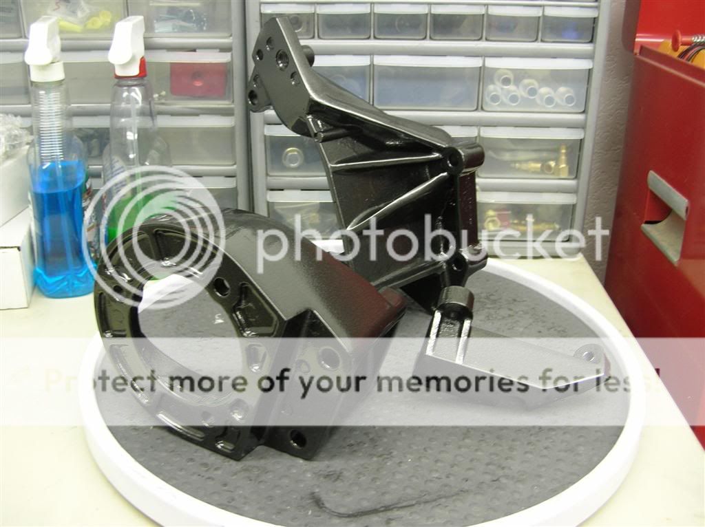
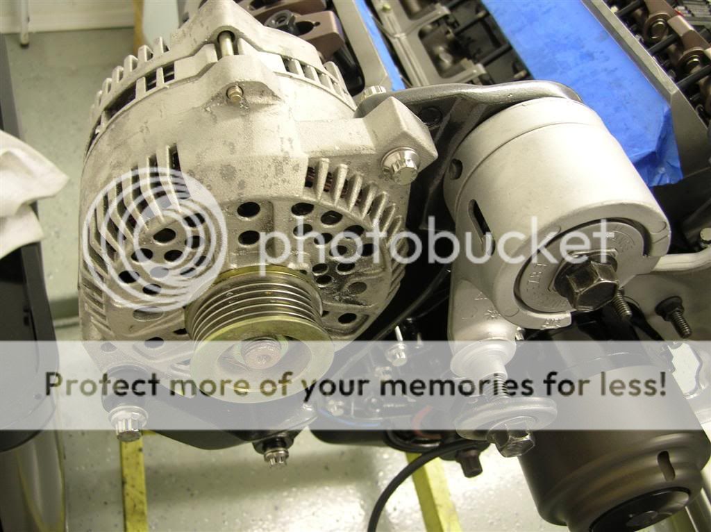
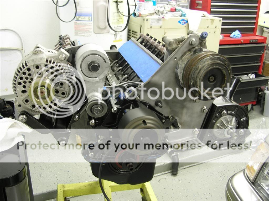
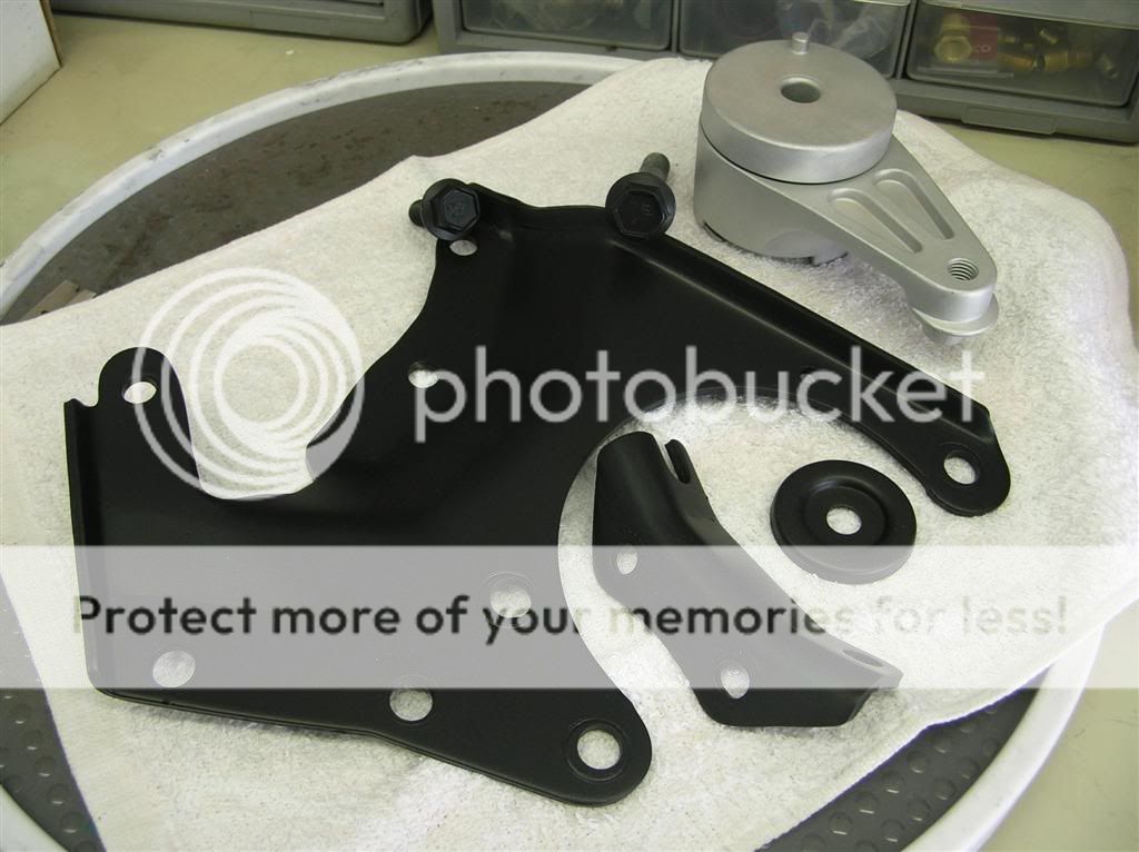
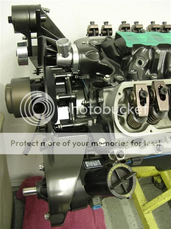
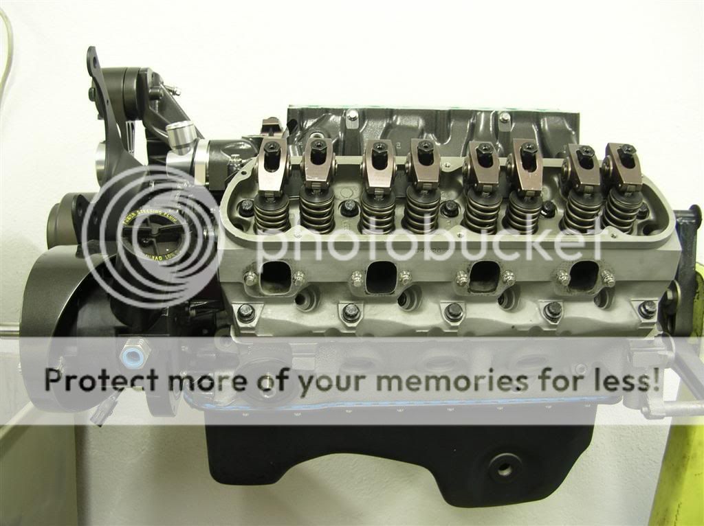
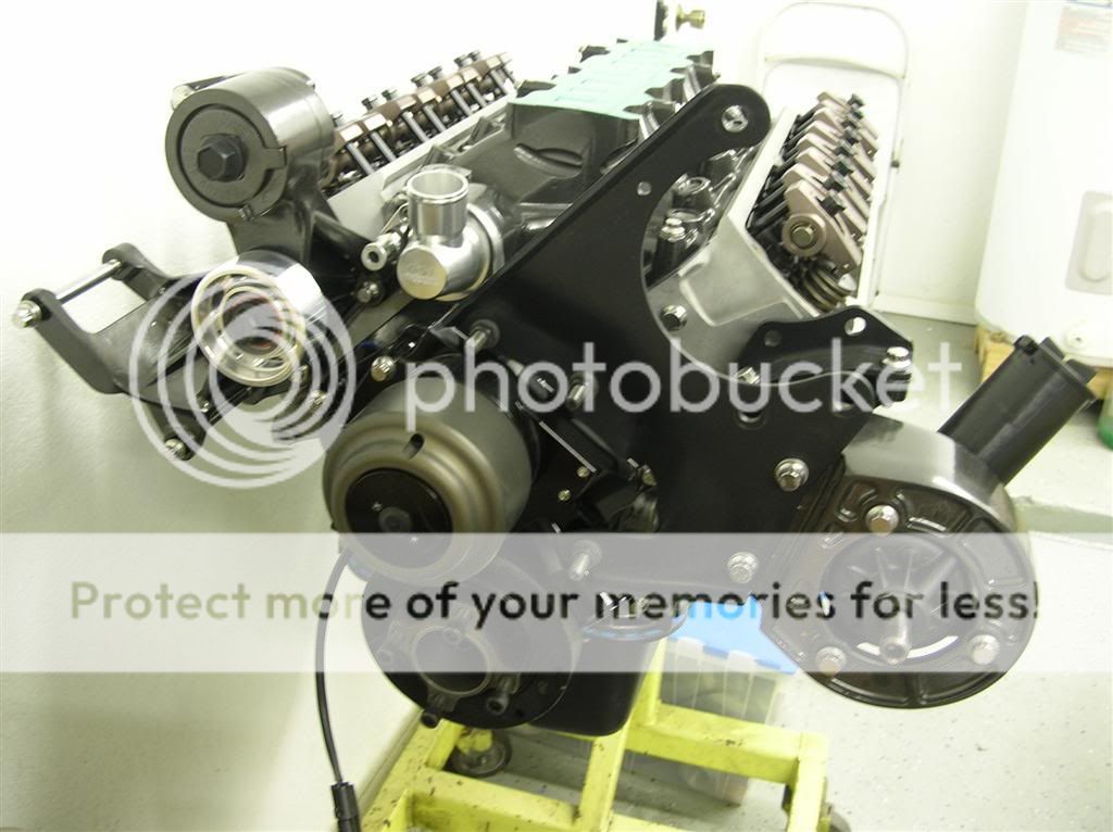
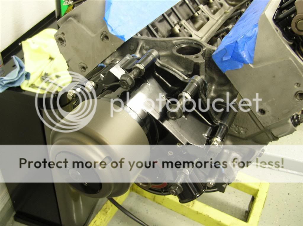
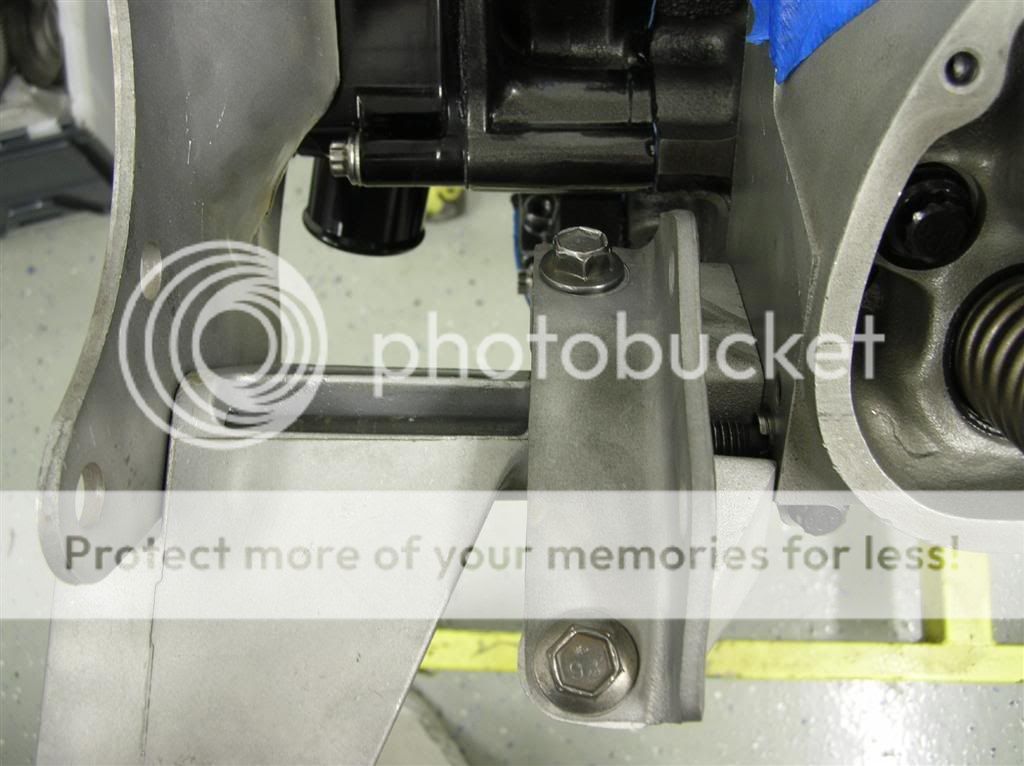
So, I began trying to figure out how the hell the damn fox bracketry goes together - I've been workong on SN95 5.0s for so long that I forgot. I eventually figured it out and started measuring bolt pitch and length. I obviously don't have all the correct fasteners here either, so I'll be ordering them as well.
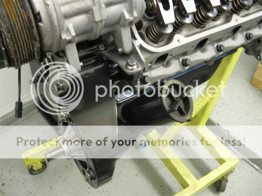
You can also see in this picture how much I had to cut up the factory steel bracket to make it clear the Meziere water pump.
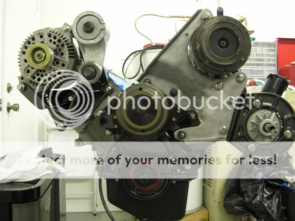
Here's from the top of the driver's side.
Paul.
________________________________________________________________________________
Here's my thread for the build of my small block Ford 306 engine for my 1989 Mustang coupe. It is a budget build with relatively simple and not-that-expensive parts in it. This is the first time I've built an engine completely from scratch, so I'm excited to do and I'm sure I will learn a lot along the way. This build has been going since December, and the first post should put everyone up-to-date.
The bottom-half components are as follows:
Production 5.0 (302) block, borded .030", align honed
OEM Crank, ground .010, polished, oil holes chamfered, balanced rotating assembly
Probe forged I-beam rods
Probe forged pistons, 4.030"
Clevite 77 main and rod bearings
Sealed Power gapless moly piston rings, 4.030"
ARP main and head studs
ARP harmonic balancer bolt
OEM harmonic balancer, 50 oz imbalance
Centerforce Billet Steel flywheel, 50 oz imbalance
Double roller timing chain
Trick Flow Stage 1 camshaft (.499"/.510" lift, 221/225 degrees duration @ .050" lift, 112* Lobe Separation Angle)
The top end consists of:
TFS Street Heat Intake
TFS Twisted Wedge Heads
TFS 1.6 Roller Rockers
Accufab 70mm Throttle Body and EGR Delete
FRPP Stainless Shorty Headers
Well, I stayed up late last night mocking up the entire rotating assembly with a buddy of mine and checking tolerances on the main and rod caps with plastigage. I also checked crankshaft endplay. My tolerances so far are as follows:
Main cap oil clearances:
Cap 1: .0015"
Cap 2: .0015"
Cap 3: .0015"
Cap 4: .0015"
Cap 5: .0015"
Crankshaft endplay:
.0038" (a little tight, spec is .004" - .008", but I will live with it. It should open up immediately upon startup and the first time I push the clutch)
Rod cap oil clearances:
#1 - .0015"
#2 - .0015"
#3 - .0018"
#4 - .0018"
#5 - .0013"
#6 - .0015"
#7 - .0018"
#8 - .0013"
Here's the block after I masked it all off and painted it cast iron grey.
This motor had OEM main cap bolts, so I replaced them with these ARP main studs for a little extra strength.
This is my friend Mike (he's a CNC machinist by trade) chasing threads on the block while I was cleaning the crankshaft out.
Here's the crankshaft (OEM) and Trick Flow Stage 1 cam.
Here's the pistons, rods, flywheel, and balancer. In that picture you can also see my oil pan and headers that I blasted with steel shot. Those will get powdercoated later.
This is a picturing of the plastigage measurement on one of the main caps.
Here's me torquing down the main caps to 70 ft. lbs. for the last of many times.
Here we are setting up the dial indicator to measure crankshaft endplay. When I did this the second time, I used my magnetic base instead of the clamp - it was easier.
To measure endplay, you set up the dial indicator, zero it, then move the crankshaft forward and backward with a prybar. Endplay should be .004" to .008" - the reason I took this motor apart was because endplay was .131" ... seriously. The crank moved so far forward when I pushed the clutch that the flywheel would actually hit the inspection plate on the bellhousing.
Next, I checked the ring gap, here's what I came up with:
Piston #1
Top Ring: .016"
Second Ring: .016"
Piston #2
Top Ring: .016"
Second Ring: .016"
Piston #3
Top Ring: .018"
Second Ring: .016"
Piston #4
Top Ring: .018"
Second Ring: .016"
Piston #5
Top Ring: .018"
Second Ring: .017"
Piston #6
Top Ring: .018"
Second Ring: .016"
Piston #7
Top Ring: .016"
Second Ring: .014" (was .016" down in the bore)
Piston #1
Top Ring: .020" (was .018" down in the bore)
Second Ring: .016"
So this is basically what I did:
First, remember these important words of wisdom... For safer engines, always use a condom.
And since I'm a bit paranoid, I always double bag it.
The first thing you need to do if you want to make this easy on yourself is buy a piston ring installer. This little tool makes it really easy to pop the rings in the grooves without scratching the crap out of the side of your ring lands. I picked this one up from Pep Boys for six bucks.
Then you need to figure out which rings go where, and how they're oriented. The ones with the shiny edge are going to be your top ones. Here is a crummy picture of the edge of my top ring.
Next, you have to keep in mind that there is an "up" and "down" side of the ring. You'll notice in this picture below that there's a tiny white circle on the ring. That circle means "this side up." On the second ring it's not as easy to see. Mine looked like a dent more than a dot.
Once you got that figured out, you can measure ring gap. This is actually really easy. All you need is a set of feeler gauges and one of your pistons. First, squeeze the ring into the bore. Be careful to not scratch the hell out of your bores with any sharp edges.
Then, take your feeler gauges and see what the largest one that you can squeeze in the gap is.
Then, using your piston to square up the ring to the bore, push the ring down a couple inches into the bore so you can take another measurement with your feeler gauges.
If you're satisfied with your ring gap, then you can install them on the pistons. Make sure to install the rings "180 apart", meaning that if the gap is on one side of the piston for the top ring, put the gap for the second ring on the other side. Also, when installing your oil rings, make sure that the ends are butted up against eachother, not overlapped. My rings came with painted ends to help you make sure they're seated appropriately.
So, that's really all there is to it. In the next installment, I'll post some pics of installing the pistons in the block. This is pretty simple though, you just need a ring compressor and a plastic hammer. You can see my one-piece 4.030" ring compressor in this picture - it is quite a bit easier than the weird ratcheting ones you can rent at the parts store. So, with that - here's a picture of all of my pistons with the rings installed and the tools I needed to do it.
At this point, the entire longblock is built, the cam is degreed and installed, and the valvetrain is completely assembled. Sorry, I don't have pics of that part of the build.
Today, I began bolting up the timing cover up.
Here's my timing cover that I powdercoated.
I used a seal installer to put the front seal in without messing it up.
Then I carefully trimmed the timing cover gasket so it wouldn't show too much once it was installed, and applied a thin bead of RTV.
Once that had "set up" a bit, I installed it on the block.
Then I put another thin bead of RTV on the timing cover and installed it on the block.
I also put some JB Weld in one coolant passage on the timing cover because it was pretty badly pitted.
I put a thin bead of RTV on the water pump gasket, and squished it on the timing cover.
Then I attached the water pump. This thing is a behemoth - it weighs TEN POUNDS.
The stupid studs are ugly and a pain in the ass. I had to run a die over all the threads and a tap through the flange nuts to make them thread easily.
Anyway, then I flipped the motor over and installed the oil pump. Always remember to take cover off the oil pump, and inspect the gerotor and casting for any nicks or burrs. The last one I got had a huge nick in it and I returned it. Then I installed the oil pickup, and re-used my one-piece oil pan gasket. I hope this damn thing seals. I put a dab of RTV in the corners for good measure.
The I put the pan on - this was the one I powdercoated a while back in flat black. I love the way the finish turned out. I tightened down the bolts in two torque sequences, 9 and 15 ft. lbs., starting from the center and working my way out.
Later on I realized that I forgot to put anti-seize on ALL the oil pan bolts, so I have to take it back off and re-do it all over again. Dammit.
So, I began trying to figure out how the hell the damn fox bracketry goes together - I've been workong on SN95 5.0s for so long that I forgot. I eventually figured it out and started measuring bolt pitch and length. I obviously don't have all the correct fasteners here either, so I'll be ordering them as well.
You can also see in this picture how much I had to cut up the factory steel bracket to make it clear the Meziere water pump.
Here's from the top of the driver's side.
Paul.
") Just the bottom end.
Just the bottom end.