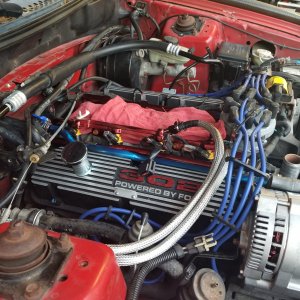
Tuning with Binary Editor

rz5.0

Legend
Joined
Mar 26, 2010
Messages
5,853
Reaction score
131
Location
Great state of TEXAS
first off i did not write this but it was my guide when i was learning to tune my 95 using QH and BE..
i have permision from the original author to post this here. for more indept explanation and questions
http://www.efidynotuning.com/forum/ is the place. some stuff will left out like graphs and stuff
this information is updated constantly at the original site so its agood idea to stop by every once in a while http://www.efidynotuning.com/ford/..
 
OP
OP
rz5.0

rz5.0

Legend
Joined
Mar 26, 2010
Messages
5,853
Reaction score
131
Location
Great state of TEXAS
Fuel 101


by Michael Decipha Ponthieux

Last updated: 8-26-2013


Lambse (Tuning Step 1)

The first step to tuning is dialing in fuel, and
the ecu controls fuel with LAMBSE!!! If you've never
tuned an engine before its imperative that you understand fuel CAN ONLY be dialed in on a WARM ENGINE. A
Cold engine will require significantly MORE fuel than a stabilized warm engine.

Lambse is the AFR (air/fuel ratio) the ecu is demading. When fuel is dialed
in your wideband will match your lambse.
YOU CAN NOT ADJUST FUEL IN
ANY WAY SHAPE OR FORM UNTIL YOU KNOW WHAT YOUR LAMBSES ARE!!!
with null
multiplier's your LAMBSE will be what your demanding in your fuel table
you
adjust your fueling to make your wideband MATCH your lambse, again,
you
adjust your fueling to make your wideband MATCH your lambse, repeat,
you
adjust your fueling to make your wideband MATCH your lambse
you adjust
your fueling to make your wideband MATCH your lambse


do
not
change the maf curve to get the wideband to spit out the afr you
want
adjust the maf curve or injector values to get the
wideband to spit out the afr the ecu is telling it to (LAMBSE)
the
LAMBSE is the AFR the ecu is DEMANDING, if your lambse is 17 at wot and your
wideband reads 14.5 at WOT then you are RICH and you need to pull some fuel out

just for clarification, the 17:1 at WOT was my example to show you that the
wideband reading means nothing if you don't know the lambse, no one in their
right mind would demand 17:1 at WOT
13:1 is more like it, to further that,
most engines running at 17:1 at max engine effeciency aren't usually too happy
and usually sputter breakup pop misfire etc..
likewise, if your LAMBSE at
WOT is 8 and your AFR(wideband) is 12.5, you are LEAN and need to add fuel

again, no sane person would demand 8:1 AFR at WOT, im using this extreme to
express the importance of LAMBSE!!!
this process is how you dial in fuel,
YOUR FUEL IS NOT DIALED IN UNTIL the wideband matches lambse

when this happens your fuel trims "KAMRF" will be very near 1 in
closed loop at all conditions
and the lambse that the ecu is demanding
during closed loop will be the actual AFR
once more, you adjust your fueling
to make your wideband MATCH your lambse
for all conditions, the lambse is
the afr the ecu is demanding
multipliers modify lambse, THEY
ARE INCAPABLE OF DIALING IN FUEL
, for example, if your lambse at WOT is
13 and your wideband is reading 13.5, your fuel is off by (13.5/13=1.038%)

changing the WOT fuel multiplier from 1.00 to 0.96 will reduce your LAMBSE
to 12.47 (13 * 0.96) and your AFR will drop to 12.94 , HOWEVER, the gap between
lambse and the wideband will still be off by the same percentage
(12.94/12.47=1.038%)
thus you hadn't dialed in fuel as your fuel is still
off, the ONLY two methods of ADDING MORE FUEL is by
either INCREASING the MAF flow or by REDUCING INJECTOR
SLOPE(S)

even with known values fuel is seldom dialed in,
typically its lean on the big end, take a stock supercharged lightning for
example, they demand 12 LAMBSE at WOT yet they only get 14 AFR
why i bring
up the lightnings? I find that just incredible and since they come stock with
the 90mm meter thats many folks use which BTW has the maf curve dialed in
perfect on the trucks
side note: typically reducing the high slope to 34.5
and the low slope to 36 on a stock lightning will have the fuel perfectly dialed
in!!!
NOTES:

if you input the actual flow values for your injectors from a
flow bench as well as the maf values from the flow bench your fuel will probably
be off a tad, it should be perfect in a perfect world but we don't live there. A
flow bench has nothing to do with injectors or a curve or anything, a flow bench
just measures flow, a good starting point but thats it Free reving an engine to
dial in the maf meter is a very valid and effective means of creating the curve
down low, you can typically dial it in enough to drive it out of state This is
maf not speed density, the maf measures airflow, it doesn't matter if your
engine is at 2v on the maf at a steady 60mph cruise or if its at 2v on the maf
free reving at 4500 rpm. Its still flowing the same amount of air, a non
lab-spec wideband is not as accurate as a narrowband at finding stoich, a
narrowband ONLY measures stoich You can't use them to dial in fuel for anything
other than stoich, however, you can should always use the narrowbands to verify
the wideband is accurate If the narrowband voltage isn't over 0.8 volts at WOT
then it would be wise to start snooping around and questioning the wideband
could also be a faulty hego ground (check out hego101 for more details).

Changing the injector slopes DOES NOT CHANGE LAMBSE.
Adaptives does not change anything, it only closes the gap from lambse and
afr
PW is irrelevelt, thats the beauty of mass air, if the fuel is dialed in at
180kg/hr then its dialed in at 180kg/hr, rpm or pw is irrelevent
Fuel is proportionate to airflow the ecu will adjust pw for the rpm to reach
the same lambse, thus mass air flow
Think of the breakpoint as an amount of fuel, because thats exactly what it
is, in the older ecu's with a breakpoint function the breakpoint does

actually get effected by rpm but its very minute, this is exactly why you
can't convert from a breakpoint scalar to function
in open loop, lambse1=lambse2

Injector Slopes

The injector HIGH slope is the actual flow rates of the
injector, typically this would be the same value as the injector is rated for
(ex: 30lb injector would have
a high slope of 30, a 60lb injector would have
a high slope of 60, etc...)
the low slope accounts for non-linearities at
low pulsewidths, at low pulsewidths an injector acts as a large injector
spraying more fuel, so to compensate
you will have a low slope with a value
HIGHER than the high slope. Typically the low slope is approximately 15% larger
than the high slope. So a 30lb injector
would typically have a low slope of
30*1.15=34.5, a 60lb injector would have a low slope of 60*1.15=69 etc...

now the further apart the low slope is from the high slope the more
influence the breakpoint will have, thus IT IS IDEAL AND HIGHLY
RECOMMENDED
to have the
low slope AS CLOSE AS POSSIBLE to
the high slope, this will insure your fueling is not doing anything odd at the
breakpoint
changing the fuel pressure will change the
slopes

for ballpark quick adjustment, I compensate 1% per
psi, so if you up the pressure from 40 to 60, i would multiply the slopes by 1.2

if i drop the pressure from 40 to 20, i would multiply the slopes by 0.8, if
i went from 40 to 45 the i would multiply by 1.05
not exact, but good enough
for government work
MAF Transfer - Dialing in the MAF

its very easy to tell if the maf
curve is accurate
, at wot with a steady lambse, your AFR will stay
consistent

if your LAMBSE is at 13 and your wideband AFR is 14 but
stays there consistent then the maf curve is accurate, you can
very simply
reduce your high slope and get your 14 AFR wideband reading down
to exactly 13 that the ecu is demanding (LAMBSE) it to be
LAMBSE's in closed
loop are based purely on hego feedback, when in closed loop your lambse's will
jump around to hit stoich
once it does, adaptives will update the KAMRF's,
when in closed loop you do not need to dial in fuel, the KAMRFs will do that for
you!!!
once you gather sufficient KAMRF data you use that info to dial in
your fuel

Note: The highest MAF voltage in the MAF transfer must be
maximum the ecu allows!!!! NO EXCEPTIONS!!!
This will be approx. 16 volts
for EEC-4 and approx. 5.1 volts for EEC5
The MAF curve must be in
chronlogical order, thus all numbers must be in order from least to greatest,
YOU CAN NOT HAVE A LOWER FLOW FOR A HIGHER VOLTAGE!!
else the ecu will reset
everytime it reaches that point

for those that don't have a known curve
i recommend to dummy down the maf transfer to only a few points in half volt
intervals like this:
16.0 volt = 1600
5.0 v = 1600
4.5 v = 1200

4.0 v = 1000
3.5 v = 800
3.0 v = 600
2.5 v = 400
2.0 v = 200

1.5 v = 100
1.0 v = 50
0.5 v = 25
0 v = 0
0 v = 0
0 v =
0
0 v = 0
0 v = 0
etc, everything below set to 0v and flow = 0, you
can now work your flows much easier, thats decipha's 2nd law of dialing in a MAF


why bother with adjusting 30pts on a maf curve if you can change just 3
injector values and your fuel is perfect every time? with a known curve you can
calculate hp from airflow, you'll also find that the transients are much more
accurate and the vehicle just runs 'smoother' your afr will also be much more
consistent, you wouldn't need to run the curve threw anything to straighten it
out as it would already be perfect, also you can use the hegos to see where your
WOT fuel is, if your kams are at one then you don't even need a wideband as your
wot fuel is perfect, for newer 94+ ecu's that have inferred load you wouldn't
have to spend hours dialing in inferred load as the only changes would be where
the engine became more effecient, typically 3/4 throttle on up, that way if your
maf sensor ever fails you can still drive the car with no problems, you can also
find if you have any turbulance in your intake piping as the maf curve would
have spikes in it, you can then clock the maf and know exactly where its
happiest at
so if you can get by with dialing in fuel using the slopes and
breakpoint, that is your best bet
 
OP
OP
rz5.0

rz5.0

Legend
Joined
Mar 26, 2010
Messages
5,853
Reaction score
131
Location
Great state of TEXAS
[h=4]Wideband/Narrowband Tuning[/h]A narrowband will report a stoich switch
before a wideband will, if it doesn't then something isn't right
a widband
is nice but it not absolutely necessary to dial in fuel, with a known curve you
can watch the kams peal the fuel curve into place
the easy way to tell if
you maf transfer is correct is that your wideband AFR will stay consistent, if
your fuel is constantly jumping all over the place
then your maf transfer is
off, but if your LAMBSEs are static and your AFR is off by a percentage then you
can make that correction with the SLOPE(s)

for example, lets say you
have your fuel table setup so that from 0 to 75 perload your LAMBSE is 14.64, at
90 to 105 load LAMBSE is 12.8, 120+ load LAMBSE is 11.8 (see A9L2 for example)

with all lambse multipliers null (set to 1 = no effect on lambse) including
the global open loop fuel multiplier scalar null (set at 1.00) your lambse will
be what we demanded in the fuel table
at WOT lambse drops to 11.8 (perload
exceeds 120) yet the wideband stays consistent reading 15.5 AFR, you can very
easily drop the high slope from say 40 to 34.5 and in the next pull the WOT

AFR will be exactly 11.8, now everything over the injector breakpoint
is going to have a kam correction of 1.00 since your linear flow fuel is dialed
in !!
The only 2 variables remaining are the low slope and breakpoint, I
start off by setting the breakpoint high, say 0.000020 (GUFB = ~6) for example,
then adjust the low slope to
get idle right where it needs to be, I then re
enable closed loop and let the hegos and adaptives dial in the fuel, once the
kams have learned you can organize the
mafv numerically in the datalog and
see how the kams have adapted, if you have a kam correction less than 1.00 in
the lower voltages of the maf curve
then you know you need to increase the
low slope, REMEMBER, you must dial in the low slope BEFORE you can dial in the
breakpoint as it will be constantly moving
once you have the low slope
dialed in and the high slope dialed in you'll see exactly where the breakpoint
is as the KAM's will not be 1.00 in that MAF voltage range
[h=4]Open Loop / Closed Loop[/h]In open loop the lambse's do not respond to hego
feedback, the lambse calculated from the fuel table(s) and multipliers is what
you get
since the hegos are cold during startup all ecu's crank into open
loop fuel mode, one can logically figure out that since the hegos can
only
report STOICH, that open loop must be entered at WOT and high loads as well
where enrichment is needed (more fuel than stoich)

during closed loop
the ecu constantly adds and subtracts lambse to get the hego to switch
if
the hego is lean ( < 0.4 volts) then the ecu drops the lambse to enrichen the
mix until the hego switches rich ( goes above > 0.4 volts)
once the hego
has switched rich, the ecu then increases lambses to get it to switch lean again
in a never ending closed loop
once the hegos are controlling
fuel correctly, the ecu will save that fuel correction in the KAMRF data and use
it the next time the ecu is in that cell (load and rpm range)
the
narrowbands and ecu can dial in your fuel much more accurately than a human can
by looking at a wideband and making adjustments
[h=4]Closed Loop Tuning / KAMRF[/h]by datalogging and comparing MAF voltage to
KAMRF we can dial in fuel perfectly
but since the hegos only report stoich
they can not be used to dial in WOT fuel... or can they?
the beauty about
mass air is that you tune the ecu to the peripherals not specifically to the
engine
by this i mean you don't dial in a VE table to calculate fuel like
you would in a speed density setup
once you have your maf and injectors
dialed in, so long that your not exceeding their capacity, your fuel will
be exactly where you set it

its highly recommended to have a wideband
for dialing in WOT but if you don't have a wideband you can still dial in your
fuel by letting the hego's do it for you
the ecu will default to open loop
at WOT, in order to force closed loop at wot you MUST set the WOT
Breakpoint (threshold) to max either 5.1 volts or 1023 ad counts
since
relative_throttle position can never reach that the WOT flag will never be set,
you must ALSO disable the OL vs RPM and OL vs ECT functions from forcing you
into open loop
the easiest way to do this is to set the time delay scalars
to 20 seconds, you can now use the hegos to dial in WOT fuel, it would be very
wise to pull a few degrees of timing out
to prevent a bunch of heat in the
engine, an engines burns hottest at just a tad leaner than STOICH, and we all
know HEAT MAKES POWAH
so by pulling out say 6 degrees or so you will reduce
the amount of heat in the engine and make it safer to beat on at STOICH
for
example, with a dialed in low and high slope your kams might look like this


at 1.5 mafv and below, the kams fluctuate between 0.97 to 1.03 which is
perfectly acceptable
at 1.8 mafv kams=1.05
at 2.0 mafv kams=1.06
at
2.2 mafv kams=1.04
from 2.3 to 5.0 mafv kams fluctuate between .98 and 1.02


you then know you need to reduce the breakpoint to give it a little more
fuel where the slopes meet which is approx. 2.0 mafv in the example given


think of it like this

low slope=low load, cruise and idle

high slope=high load, wot and aggressive acceleration
breakpoint, is the
center of where it mixes both together


in every tune i make, i demand a set value across the table for a specific
perload for example:
I demand 14.64 (stoich) up to a perload of 75% of the
maximum engine load (no boost) and 12.8 at perloads of 90% and greater
I
drop the lambse to 11.8 at a perload of 120+ (n/a engine can't reach perload
greater than 100% when tuned correctly)
the O/L fuel table fn1362 and the
stabilized fuel table fn1360 do the same thing, only different is stabilized
table has rpm input instead of ect, at startup the base fuel table is used
regardless until the ECT stable flag is set
in which it switches to the
stabilized fuel table fn1360, as long as you reasonable values in the tables for
it makes no difference tune wise
Note: The RPM vs Load Open Loop Function is
ONLY ACTIVE once the ECT Stable Flag is set, setting the function to all 0s will
not force open loop until the ECT Stable flag is set.
the lambse is the afr
your telling the ecu you want, if your lambses are 12.5 at WOT and you want them
at 11.8 you need to go to the fuel table and change it from 12.5 to 11.8 in
those cells
its very difficult to get the fuel dialed in with closed loop
throwing you around, once you get your fuel right you can then allow closed loop
and adaptives to do their thing and dial your fuel in perfect, only a narrowband
can dial your fuel in perfect, unless you want to get a lab spec wideband and
spend hours makes decimal changes to your fueling
[h=4]STFT to Lambse[/h]Short Term Fuel Trim is the equivalence ratio of stoich,
It is the exact same representation of Lambse except in percentage instead of
lambda.
To put this into perspective, lets say at WOT we have a perload of
140
This gives us a LAMBSE of 11.8 from our example base fuel table we
described above

14.64 / 11.8 = 1.240% fuel equivalence ratio (STFT)

thus we will have a STFT of 24% since we are adding 24% more fuel


Now, lets say for example, we are in closed loop and our STFT has a
negative value of -18

14.64 * 1.18 = 17.27 (Lambse)

as you can
infer, a negative STFT means its removing fuel, so you MULTIPLY to get the
lambse
a positive STFT means it is adding fuel, so you divide to get the
Lambse
So lets say for example, we have a STFT of 18

14.64 / 1.18 =
12.4 (Lambse)

for quick reference heres a table to break it down and
help understand it better
11.71 = 14.64 / 1.25


STFT
Lambse

-1
14.78 = 14.64 * 1.01

-2
14.93 = 14.64 * 1.02

-4
15.22 = 14.64 * 1.04

-8
15.81 = 14.64 * 1.08

-12
16.39 = 14.64 * 1.12

-16
16.98 = 14.64 * 1.16

-18
17.27 = 14.64 * 1.18

-20
17.56 = 14.64 * 1.20

-25
18.30 = 14.64 * 1.25


0
14.64 = 14.64 / 1.00

1
14.49 = 14.64 / 1.01

2
14.35 = 14.64 / 1.02

4
14.07 = 14.64 / 1.04

8
13.55 = 14.64 / 1.08

12
13.07 = 14.64 / 1.12

16
12.62 = 14.64 / 1.16

18
12.40 = 14.64 / 1.18

20
12.20 = 14.64 / 1.20


25

[h=4]SUMMARY[/h]just a quick recap,
YOU CAN NOT DIAL IN FUEL USING THE WOT
FUEL MUTIPLIER OR THE FUEL TABLES!!!
the wot multiplier and fuel tables only
modify lambse THEY DO NOT DIAL IN FUELING!!
you can use the wot fuel
multiplier if you want, in fact I use it on all my mail order tunes, but
remember though its a multiplier on lambse it can't dial in fuel
so remember
if your demanding 13 and your wideband is saying 12 even if your in boost, your
running rich, once again the purpose in this thread is that the wideband reading
is
useless without knowing the lambse, their is no possible way to know if
your rich or lean since its relative to lambse


if you want a WOT AFR
of 11.8 and your wideband reads an AFR of 11.8, yet the LAMBSE is 12.5 (the
computer wants 12.5 AFR) THEN YOU ARE RICH and you need to change your fuel
table to 11.8 instead of 12.5 and then readjust your fueling so your wideband
then reads 11.8 again which would coincide with your lambse, since your 1.059%
richer now if you just changed the lambse to 11.8 without changing your fueling
you'll be down to around 11.14
LAMBSE is the AFR the ecu is
demanding, widebands read the actual AFR, thats why you dial in fuel by
getting the actual AFR (wideband) to match the demanded afr LAMBSE
table
rescaling has no effect on FUELING
for the record, no one has to rescale any
tables, its ONLY done to gain more control, if you want to do it the
quick way you can simply increase the sarchg (cubic inch displacement scalar)
and adjust your tables accordingly, same principle
LAMBSE is the afr you
tell the ecu you want, once fuel is dialed in correctly, the wideband will spit
out the same AFR as LAMBSE
the lambse should be whats in the fuel table
unless your in closed loop and its varying around stoich or if theres a
multiplier thats modifying the lambse, like the wot multiplier, global fuel
scalar, startup enrichment, lug multipliers, etc..
the injector slopes have
nothing to do with lambse
its often easiest to get fuel close in open loop
then enable closed loop and use the kams to mold the fueling into place
perfectly
the older ecu's used rpm as a variable for the breakpoint, where
as with the newer ecu's its static thus the single breakpoint lb fuel scalar
 
OP
OP
rz5.0

rz5.0

Legend
Joined
Mar 26, 2010
Messages
5,853
Reaction score
131
Location
Great state of TEXAS
[h=2]Timing 101[/h]
by Michael Decipha Ponthieux


Last updated: 9-10-2013
[h=3]Premise[/h]Ignition timing makes torque, and torque makes power!
at low
loads idle and part throttle you can usually demand a crap load of timing, i've
often put sbf's at 50 degrees during cruise and 42 at light acceleration, 40 at
moderate acceleration and 38-36 at heavy acceleration, and idle at 34+ above 1k
rpm, the most significant factor to determine ignition timing will be the
combustion chamber/cylinder head design, this can vary significantly, an MBT
reference chart is listed at the bottom of this page.
over advanced timing
at very low loads is often confused for valve train rattle, DO NOT CONFUSE THE
TWO, it may not be subtle at first, but with time may poke its head, if you are
heavily advanced at very low loads and hear what sounds to be a valve train
rattle, verify it is the valve train by removing the spout, or pulling out 10
degrees of timing during that condition
WOT timing will be significantly
effected by the cylinder head, reference the chart at the bottom of this page
for more details, just remember there's no point in demanding any less than the
amount of timing you demand at WOT for part throttle at the same rpm as that's
just reducing torque, the amount of timing at WOT should be the absolute lowest
timing the engine should ever see at that rpm other than idle
now keep in
mind cylinder head, stroke ratio, intake design, cam profile, runner length,
plug type, coil strength, gearing, and a bunch other variables will directly
affect the safest amount of spark you can demand, the largest influence will be
the OCTANE LIMITIATION OF THE FUEL YOUR BURNING
also keep in mind where your
peak efficiency is (where the engine makes peak torque) at max efficiency you'll
typically need to pull out 2 or 3 degrees to prevent detonation (if your are
running timing on the very edge), this can be easily observed on a dyno or by
feeling and listening to the engine
now this might not exactly apply to
those in california or other states that have to pass emissions, but for the
sake of being politically correct, the tune you use for emissions testing should
be labeled 'emissions tune'

Note: retarding timing reduces emissions,
its not uncommon for folks to LOCK OUT timing to 10-15 degrees for emissions
testing.
[h=3]MBT - Maximum Brake Torque[/h]the biggest mistake a bunch of tuners make is
thinking that more timing=more power, that's correct to a point, but like
everything it's a trade off, the idea is to get as close to MBT as possible, MBT
in the context i'm using it for is max brake torque, just because an engine can
handle more timing doesn't mean that the additional timing is helping, over
advancing an engine is a common mistake that i see often, so keep that in mind

MBT is defined as the MINIMUM amount of ignition timing that results
in the MAXIMUM amount of engine torque increase For
clarification, this does not mean the maximum amount of ignition timing that
equals the aboslute maximum amount of torque. MBT is the point where removing 1
degree of timing will result in a greater torque loss than increasing 1 degree
of timing. For example: lets say at 3000 rpm and 70 load you make:
258 ft lbs @ 26 degrees
275 ft lbs @ 27 degrees
292 ft lbs @ 28 degrees
296 ft lbs @ 29 degrees
281 ft lbs @ 30 degrees

Although 29
degrees created the most torque, 28 degrees is MBT since decreasing to 27
results in -17 ft lbs lost and increasing to 29 degrees only results in a gain
of 4 ft lbs
MBT can be summarized as when pulling a degree has more of an
effect than increasing a degree.
there's been quite a few times where i've
pulled timing and picked up mph's in the 1/4 its not uncommon so be warned

on a dyno you can easily find where MBT is by using the method described in
the above example, on the street it may be harder to tell, typical dyno loading
allows for an engine to hit MBT where that's not possible on the street with
actual loading as it will almost always result in pinging thus detonation before
getting there
when i hear an engine ping lightly i pull out at least 2
degrees, if its a hard knock i yank out at least 4+, to each their own, this is
just my quick adjustment method
a low load knock is by far the hardest for
an untrained ear to hear, it will to the normal person sound like a valve train
rattle, it will most notably be present during decel, keep this in mind if you
think you have a valve train issue as it could very well be over advanced idle
spark or low load spark knock you can verify by pulling the spout
a boosted
engine is an animal of a different color, boosted engines don't tend to knock or
ping for very long instead they detonate with a loud rattle or even a bang,
don't get too greedy on a boosted engine, its been said before that the general
rule of thumb to be safe is to pull out 1/2 degree for every lb of boost, that
is not the end all method to all at all, thus the need for tuning. as stated
previously there are many factors that come in to play when dealing with
ignition timing, any one of those factors can be significantly aggravated with
boost, although pulling out 1/2 degree per pound will result in satisfactory
results more times than not i always yank out a couple degrees more at first and
work my way up rather than over advancing and working my way down
on a dyno
its pretty easy to tell when your under advanced as its typical to gain 35-60
rwtq for every degree when heavily under advanced, when you get to the point
that adding a degree reduces tq minimally you know your at MBT, on boosted
engines I typically stay at least 3-4 degrees away from MBT regardless, unless I
know I have enough octane that detonation is not going to ever occur
on a
boosted engine i always use the timing at max engine efficiency 0 vac and 0
boost as my reference, as I transisition into boost i yank out timing linearly
until I reach my desired advance at the highest load the engine can reach for
that specific amount of boost, once again listen and feel, the two most
important tools in any tuners arsenal
if you find yourself surprisingly
under advancing the timing to prevent pinging you should start investigating,
don't rely on the fuel to be what its advertised to be, it wouldn't hurt to try
to clean out some carbon by heating the engine up and sucking small amounts of
water through the engine using a small diameter vac line, question the base
timing and double check it
its not uncommon for the harmonic balancer to be
slipped especially on older vehicles
modular's typically handle boost better
than sbf's so you can typically get away with pulling out less timing for boost
than with a pushrod. But keep it safe.
 
OP
OP
rz5.0

rz5.0

Legend
Joined
Mar 26, 2010
Messages
5,853
Reaction score
131
Location
Great state of TEXAS
[h=3]ECU Implementation[/h]this applies to some 92+ (superoupe, 4cyl stang,
lincoln mark 8) and ALL 94+ ecu's this DOES NOT APPLY TO THE
OLDER GUF (foxbody) ECU'S, Foxbody tuners CLICK HERE


at any given
time the actual spark delivered is the lowest spark the ecu calculates


idle (feedback) spark is calculated from the mbt
using the torque
limiting function fn799
from the following scalars
spk_load_res -
feedback spark desired torque (setting this to 0 will give you maximum idle
spark)
after fbs_entry_tc - feedback spark entry time constant
which is
clipped by spk_fbs_min - feedback spark min
and oscillated by spk_fbs_gain -
feedback spark gain
not to exceed tr_delta - feedback spark torque ratio max
delta (recommend value of 1 in all calibrations)

the mbt spark table
fn2300 is modified
by the adder for lambse function fn730
the adder for
egr function fn731
and the adder for vs fn743
its only
neccessary to dial in the MBT spark functions when you have an ecu controlled
automatic transmission


now you can't get into idle feedback spark
unless both the idle flag and the closed throttle flags are set, which is going
to be primarily due to the IDLRPM scalar and its hysteresis, just make sure your
idle air is dialed in and the idlrpm scalar has been adjusted correctly and all
should be well

base spark, the sealevel fn2100 and altitude fn2110
tables are modified by:
ect fn2120
lambse fn2140
egr fn711
and
bp bias fn712

for ease of keeping track of timing many folks just set
the base tables high, say 60, ecu uses the lowest calculated spark


borderline knock is the most used table as it has the most inputs for
knock suppression, the borderline knock table is what i use and recommend
everyone else to as well

the borderline knock table fn2200 is modified
by the following which are sub-modified as noted:
ACT retard is fn725a
multiplied by fn2230 (i recommend setting fn2230 to all 0.1s and setting the act
retard function to go like, 254 = -80, 130 = -40, 94 = 0, -254 = 0, all else
below repeat)
lambse fn2240
ECT fn724a multiplied fn2220 (i recommend
setting fn2200 to all 0.1s and setting the ect retard function to go like, 254 =
-80, 234 = -40, 224 = 0, -254 = 0, all else below repeat)
transient load
fn2250 sub-mod by the lug timer fn723
egr fn721
bp fn722

for
example: lets say your idling at 750rpm @ 16 load, looking in the mbt table we
get an interpolated value of ~33 degrees, the scalar spk_load_res is set to .9
which is the torque ratio from mbt the ecu is demanding, it references fn799
spark mbt retard for torque limiting to see how much to adjust the mbt spark to
get its desired tq ratio, lets say .9 = -15 in the fn799 function, this gives us
an idle spark of 18

be careful with the spark mbt table fn2300 as thats
how torque modulation is referenced to variate transmission tv pressure on ecu
controlled automatic trans equipped vehicles

again, the ecu uses the
lowest calc'd spark
fn741 is the low load limit spark used when air mass is

below the stab_lold_am scalar, most set this function high if
not
already done in the stock cal to null it (i recommend a value of 63.75)


tip in retard yanks timing when the throttle is opened beyond the scalar

kacrat - tip in throttle position
which can be disabled by maxing it out
~5.1v or 1023 ad counts (this scalar DOES NOT get referenced in CBAZA)
else
the tip_min_spk scalar is the minimum spark demanded WHEN a tip in has occurred,
not how many degrees to retard as many think, you can set this to 60 to null tip
in retard if you don't have kacrat available in your def file

you then
have your global spark modifiers like:
spk_add - usually 0
spk_mul -
multiplier usually 1
spuclp - max spark clip usually 55 or so
splclp -
min spark clip usually 0
later on you then have individual cylinder spark
control

also keep in mind the mbt retard limiter function fn799
and
spark derived torque ration fn766 should mirror each other

spark
oscillation modulation is a steady state spark modifier to aid in stabilizing
the current rpm, the SOM table fn2020 is modified by fn746 and fn745, i
recommend setting the SOM table to 0

set the base timing
to ten (10), not only is the base timing important, but the orientation of the
distributor is as well so injector timing is accurate

install the dis as
per the ford specifications
 
OP
OP
rz5.0

rz5.0

Legend
Joined
Mar 26, 2010
Messages
5,853
Reaction score
131
Location
Great state of TEXAS

Idle Air 101
by Michael Decipha Ponthieux

Last updated: 8-22-2013

[COLOR=#16545]Note: all writing in this color does not apply to older ford ecu's
(such as the foxbody ecu)[/COLOR]

Idle Air Control

the idle air neutral function FN875N and drive
air function FN875D contain the actual air mass needed to reach a desired
rpm WHEN THE ENGINE IS AT STABILIZED WARM IDLE ONLY and the isc
table multiplier FN1862N cell(s) in use is at 1
before continuing be
sure you fully understand this statement

the idle air neutral function
FN875N and drive air function FN875D contain the actual air mass
needed to reach a desired rpm WHEN THE ENGINE IS AT STABILIZED WARM IDLE
ONLY
and the isc table multiplier FN1862N cell(s) in use is at 1

these functions are only dialed in ONLY WHEN THE ENGINE IS AT STABILIZED
WARM IDLE (typically 200-220 degrees ECT), which means the engine has been
running at least 15 minutes and the throttle has been closed for at least 2
minutes, and the FAN HAS BEEN OFF for at least 2 minutes ***you
can not dial in idle air when the fan is on due to the extra loading!!! there is
seperate values for that [COLOR=#16545]FN885 & FN822B[/COLOR]


now you can ONLY dial in idle air AFTER your
idle fuel is dialed in, if your in closed loop at idle your fuel kams should be
near 1, if your kams are more than 5% off at warm idle you need to dial your
idle fuel in first.
YOU CAN NOT ADJUST IDLE AIR WHEN IDLE FUEL IS NOT
CORRECT!! this is because any correction to idle fuel will alter the idle air
requirements
now ASSUMING you've got your idle fuel dialed in, get her up to
WARM operating temp and stabilized idle, again FANS OFF


make sure your average rpm is within 50ish rpm of demanded idle which will be
the scalar NUBASE when in neutral, be sure there is no rpm adders in
effect (such as fn825b ACT adder, fn825a ECT adder, fn821a voltage adder, fn880
time adder, fn890 bp adder) you can verify there is no adders in use by logging
the payload DSDRPM, dsdrpm is the rpm the ecu is trying to target,
with no adders in neutral DSDRPM will be the same as NUBASE, +/- 8
rpm due to it being two different memory structures

the tps at idle
closed throttle means nothing so long as its between the TAPMIN (tps
minimum) and TAPMAX (tps maximum) if the tps is not within that range
then the logged tps value will be the value of the scalar RATIV (failed
tps value) verify the tps does not match RATIV at closed throttle, if it
does then more than likely the tps value is too low, to fix this you can simple
reduce the min tp scalars VTAP1, VTAP3, TAPMIN, to put the tps sensor
back in range, i usually set all 3 of those scalars to 0.4 volts (82 adcts)

folks used to believe the tps had to be at .99 for max power, thats complete
crap anyone feeds you that garbage you punch them in the mouth as per decipha,
the ecu takes the lowest tp voltage it gets and uses that as 0 relative position
which can be logged as the payload TP_REL, this is known as ratch


now with the engine at stabilized warm idle with no adders and no fan,
keep an eye on the payload AM air mass value if you do not have access to
the air mass payload than keep an eye on the MAF payload, if you don't
have access to maf you'll need to log the maf voltage (imaf, mafv, or
vmaf
) then go calculate the air mass from it, if you can't log maf voltage,
you'll need to probe the maf sensor and subtract approx .14 volts from it
then go look up that voltage in your maf transfer FN036 to know the air
mass
in any case, you want to get an average, it doesn't need to be exact
just a good guesstimate average, if its jumping around quite a bit then chances
are your getting a bit of turbulence through your maf and it would be wise to
install a mesh screen to smoothen out the airflow, prior to installing a screen
you can try 'clocking' the maf by loosening the clamp and 'turning' it until you
get THE HIGHEST POSSIBLE MAF at idle which should be where its most stable,
IE... not jumping around alot, a .03 fluctuation is about normal
log
the iscdc as well or the "ISC duty cycle", you'll need this value to get
the correct throttle body airflow value ITHBMA the isc duty cycle should
be pretty consistent, [COLOR=#16545]if its not you need to tame your idle
by increasing the idle air correction constants scalars TC_OVER and
TC_UNDER
temporarily setting the SPK_FBS_GAIN (feedback spark
gain) value to 0 so that the ecu doesn't throw around spark at idle, keep in
mind on a large lift cam or a stupid overlap cam setting the gain multiplier to
0 will probably make it surge, if this is the case you will need to increase the
gain, a value of 1 usually works out well for most engines[/COLOR]
if that
still doesn't stabilize the iscdc you may need to disable idle air kam
correction by either setting both the min correction PSIBRN scalar to 0
as well as the max PSIBRM scalar to 0 or if you have access to the isc
global multiplier scalar IDCMUL set it to 0 and global isc adder scalar
IDCOFS set to 35, if you had to set both correction clips to 0 and still
can't get the idle to stabilize then you can temporarily clip the isc min duty
cycle by increasing the DEBYCP scalar, keep increasing it until the idle
is stable
Note: for those with really stupid cams, you may need to
permanently keep these correction scalars to 0 for a stable idle, if idle air is
dialed in then you won't need correction anyway under most conditions, or you
could possibly reduce the correction limits PSIBRN and PSIBRM,
values of .05 and -.05 usually work out pretty well for most engines with stupid
cams and still allows it to adapt to air changes
 
OP
OP
rz5.0

rz5.0

Legend
Joined
Mar 26, 2010
Messages
5,853
Reaction score
131
Location
Great state of TEXAS
once you have the idle stable it would be ideal to get the
iscdc between 25% to 35%, reason being is that it will allow headroom for
cold enrichment, if its below 25% then close the throttle body stop (reduce
air), if its above 35% you need to open the throttle body stop (increase air)


It is imperative that the above be followed, if the
ISCDC is below approximately 20% then the IAC valve is completely closed
and the ECU cannot control the idle.

now with a stable AIR MASS or
MAF value and ISCDC we can input the correct info we need to let
the ecu know how to control idle correctly

go to the neutral idle air
function FN875N and put in the NUBASE value and the actual
AM value you averaged, if you only have MAF to log then you'll
need to convert from kg/hr to lbs/min by multiplying the average MAF value by
2.2 then dividing by 60
ex: your average MAF at idle was 28 kg/hr,
28*2.2/60= 1.026 lbs/min, not exact but good enough, this value goes directly
into the idle air function

next you'll need to dial in the throttle body
airflow scalar ITHBMA, the t/b airflow scalar is the amount of airflow
the ecu can not control
you can figure out how much air was coming through
the tb blade by looking up the isc transfer table [COLOR=#16545]FN8000[/COLOR] for newer ecu's or the transfer function
fn800 for the older ecu's
calculate the lb/min contribution from the
isc (known as DEBYMA) by interpolating the flow at your logged
ISCDC value
if you can log the DEBYMA payload then you don't
have to do the following, since most def's do not have access to that payload we
will calculate the isc airflow the long way
ex: average ISCDC was 35,
lookup your isc transfer, for this example, the transfer gives:
39 dc = .25
lb/min and
28 dc = .12 lb/min
so to interpolate what the flow is at
35dc,

39dc - 28dc = 11 dc difference;

now work the flow .25 -
.12 = .13 difference;

.13 airflow difference over the 11 duty cycle
difference gives us:
.13 / 11 = .0118 per duty cycle


now we
subtract our dc from the upper end of the scaling
39-35 = 4;

we now
multiply our duty cycle difference by the airflow per duty cycle

4 *
.0118 = .0472; not done yet, dont forget to subtract this from the upper airflow
value of the airflow scaling from which you interpolated your iscdc to
get the total isc airflow
.25 - .0472 = .2028
the isc valve is flowing
.2028 lbs/min of air at 35% dc

see how simple it is, just basic math,
the ecu uses the following formula

AM - DEBYMA =
ITHBMA


now subtract that value from the AM, ex:
1.026-.2028=.8232

this is the value for the throttle body airflow
ITHBMA scalar, as you can see this is the amount of air the ecu
SUBTRACTS from the AM to calculate the iscdc it needs to
get to the rpmdsd

before continuing its imperative that you fully
understand this statement, to clarify in other words, the ecu looks up the idle
air function to calculate how much airflow AM is needed to reach a
dsdrpm, by knowing what the actual AM from the maf sensor and the
amount of airflow that is going through the throttle body ITHBMA it can
very simply calculate the duty cycle needed of the isc valve (a.k.a. Idle Air
Control valve) to get the amount of air mass to reach a specific dsdrpm


you should be able to infer by now that
fn875n - ithbma = isc flow
(lookup dc from fn8000)
AM (maf) - fn875n = ipsibr (correction)


since this can be a bit confusing i will do another example, lets say
the engine has an average idle MAF of 32.32 which equals 32.32 * 2.2 / 60
= 1.185 AM at an iscdc of 17.5%, by looking in the function fn800
or fn8000 we can get the scaling values, A9L2 has the following values:


.12 lbs/min = 28dc
0 lbs/min = 10dc

which gives us 28-10=18
dc difference
.12-0 = .12 airflow difference

.12/18=.0066 per dc

now to interpolate the airflow
28dc - 17.5dc = 10.5 dc * .0066 = .0693

.12 - .0693 = .0507 lbs/min flowing through the idle air control valve when
the duty cycle is at 17.5%
am - isc air flow = ithbma
1.185 - .0507 =
1.1343
be sure you understand this before proceeding!!!

when an
engine is cold it will require more rpms to stabilize, thus we need to have a
higher rpm value with airflow for the ecu to interpolate between for the
increased engine speed
to do this, increase the NUBASE scalar by 500
rpm, once the engine has stabilized at the new dsdrpm calculate the new
average AM then insert that value and the new dsdrpm value into
the FN875N function just like you did before


NOTE: EVERY FUNCTION IN THE ECU MUST BE SCALED TO THE
ABSOLUTES, THIS MEANS THE TOP MOST VALUE MUST BE THE HIGHEST POSSIBLE INPUT THE
ECU ALLOWS AND THE BOTTOM MOST VALUE MUST BE THE ABSOLUTE LOWEST VALUE THE ECU
CAN CALCULATE, THIS APPLYS TO ALL FUNCTIONS AND ALL YEAR ECU'S
 
OP
OP
rz5.0

rz5.0

Legend
Joined
Mar 26, 2010
Messages
5,853
Reaction score
131
Location
Great state of TEXAS
once you have the idle stable it would be ideal to get the
iscdc between 25% to 35%, reason being is that it will allow headroom for
cold enrichment, if its below 25% then close the throttle body stop (reduce
air), if its above 35% you need to open the throttle body stop (increase air)


It is imperative that the above be followed, if the
ISCDC is below approximately 20% then the IAC valve is completely closed
and the ECU cannot control the idle.

now with a stable AIR MASS or
MAF value and ISCDC we can input the correct info we need to let
the ecu know how to control idle correctly

go to the neutral idle air
function FN875N and put in the NUBASE value and the actual
AM value you averaged, if you only have MAF to log then you'll
need to convert from kg/hr to lbs/min by multiplying the average MAF value by
2.2 then dividing by 60
ex: your average MAF at idle was 28 kg/hr,
28*2.2/60= 1.026 lbs/min, not exact but good enough, this value goes directly
into the idle air function

next you'll need to dial in the throttle body
airflow scalar ITHBMA, the t/b airflow scalar is the amount of airflow
the ecu can not control
you can figure out how much air was coming through
the tb blade by looking up the isc transfer table [COLOR=#16545]FN8000[/COLOR] for newer ecu's or the transfer function
fn800 for the older ecu's
calculate the lb/min contribution from the
isc (known as DEBYMA) by interpolating the flow at your logged
ISCDC value
if you can log the DEBYMA payload then you don't
have to do the following, since most def's do not have access to that payload we
will calculate the isc airflow the long way
ex: average ISCDC was 35,
lookup your isc transfer, for this example, the transfer gives:
39 dc = .25
lb/min and
28 dc = .12 lb/min
so to interpolate what the flow is at
35dc,

39dc - 28dc = 11 dc difference;

now work the flow .25 -
.12 = .13 difference;

.13 airflow difference over the 11 duty cycle
difference gives us:
.13 / 11 = .0118 per duty cycle


now we
subtract our dc from the upper end of the scaling
39-35 = 4;

we now
multiply our duty cycle difference by the airflow per duty cycle

4 *
.0118 = .0472; not done yet, dont forget to subtract this from the upper airflow
value of the airflow scaling from which you interpolated your iscdc to
get the total isc airflow
.25 - .0472 = .2028
the isc valve is flowing
.2028 lbs/min of air at 35% dc

see how simple it is, just basic math,
the ecu uses the following formula

AM - DEBYMA =
ITHBMA


now subtract that value from the AM, ex:
1.026-.2028=.8232

this is the value for the throttle body airflow
ITHBMA scalar, as you can see this is the amount of air the ecu
SUBTRACTS from the AM to calculate the iscdc it needs to
get to the rpmdsd

before continuing its imperative that you fully
understand this statement, to clarify in other words, the ecu looks up the idle
air function to calculate how much airflow AM is needed to reach a
dsdrpm, by knowing what the actual AM from the maf sensor and the
amount of airflow that is going through the throttle body ITHBMA it can
very simply calculate the duty cycle needed of the isc valve (a.k.a. Idle Air
Control valve) to get the amount of air mass to reach a specific dsdrpm


you should be able to infer by now that
fn875n - ithbma = isc flow
(lookup dc from fn8000)
AM (maf) - fn875n = ipsibr (correction)


since this can be a bit confusing i will do another example, lets say
the engine has an average idle MAF of 32.32 which equals 32.32 * 2.2 / 60
= 1.185 AM at an iscdc of 17.5%, by looking in the function fn800
or fn8000 we can get the scaling values, A9L2 has the following values:


.12 lbs/min = 28dc
0 lbs/min = 10dc

which gives us 28-10=18
dc difference
.12-0 = .12 airflow difference

.12/18=.0066 per dc

now to interpolate the airflow
28dc - 17.5dc = 10.5 dc * .0066 = .0693

.12 - .0693 = .0507 lbs/min flowing through the idle air control valve when
the duty cycle is at 17.5%
am - isc air flow = ithbma
1.185 - .0507 =
1.1343
be sure you understand this before proceeding!!!

when an
engine is cold it will require more rpms to stabilize, thus we need to have a
higher rpm value with airflow for the ecu to interpolate between for the
increased engine speed
to do this, increase the NUBASE scalar by 500
rpm, once the engine has stabilized at the new dsdrpm calculate the new
average AM then insert that value and the new dsdrpm value into
the FN875N function just like you did before


NOTE: EVERY FUNCTION IN THE ECU MUST BE SCALED TO THE
ABSOLUTES, THIS MEANS THE TOP MOST VALUE MUST BE THE HIGHEST POSSIBLE INPUT THE
ECU ALLOWS AND THE BOTTOM MOST VALUE MUST BE THE ABSOLUTE LOWEST VALUE THE ECU
CAN CALCULATE, THIS APPLYS TO ALL FUNCTIONS AND ALL YEAR ECU'S


if you have an automatic transmission, you can copy FN875N over to
FN875D now put the vehicle in gear and repeat the same procedure to dial
in the idle air drive function FN875D


NOTE: THE IDLE AIR
IN DRIVE FUNCTION CAN ONLY BE DIALED IN AFTER NEUTRAL IS DIALED IN


Its not uncommon for the ITHBMA to be off when the vehicle is placed into
gear, DO NOT ADJUST ITHBMA WHILE IN DRIVE
instead, compensate for the IPSIBR
correction with the FN875D function

Note: Typically when your idle air
is dialed in correctly and your ISCDC is less than 35%, ITHBMA
should be approx. 0.100 to 0.150 less than FN875N.

Note: The ecu
will adjust the isc duty cycle to get the rpm to dsdrpm, if you open the
throttle body set screw your are letting more air bypass the throttle body blade
and the rpm's will increase, the ecu will then reduce the isc duty cycle to get
the rpms to come back down and vice-versa

from now on all idle air
correction will be done in the multiplier table(s) [COLOR=#16545]FN1862N and FN1862D[/COLOR] or FN1861 for the
older ecu's, you adjust that table by adjusting the cell in use to get the
isckam# and ipsibr to stay near 0 you are doing so to
compensate for the additional friction and lack of efficiency due to the engine
being cold that table is multiplying the stabilized engine idle airmass
FN875 to compensate for the cold engine idle

FOR NOW ON ALL
YOUR IDLE AIR CORRECTION WILL BE DUE TO THE MULTIPLIER TABLE(S)
you'll need
to log a cold startup in order to dial in the complete table the objective is to
get the isckam and the ipsibr to stay near 0 you do this by
adjusting the multiplier table to get your rpm to match dsdrpm if
your dsdrpm is too low when cold then you need to increase the rpm adder
functions accordingly


FN825B "ACT Adder"
FN825A
"ECT Adder"
FN826A "Startup ECT Adder"
[COLOR=#16545]FN821A "Voltage Adder"
FN880 "Neutral Timer
Adder"[/COLOR]

this all may sound like alot but for all of the 2 minutes
it takes your completely done with dialing in idle air, the only time you'll
ever have to revisit this is if some one decides to mess with the set screw
later down the line
you should notice now that your tip-in throttle response
is improved, this is due to the ecu knowing the exact air requirements needed
off closed throttle, so it can calculate fuel more consistently at idle tip in


now if you have a cam that has a large idling range, and you don't
disable the air mass correction then you'll need to adjust the isc rpm deadband
RPMDED to a higher value so adaptives doesn't constantly swing your idle
around
if you want to get more advanced into the idle air logic, you can go
manipulating the update rate function FN860, increasing the loops will
make a correction slower, you also have the KPSI** scalars which control
the rate at which the correction is applied, you can decrease those correction
values to stabilize idle as well

if your using my
A9L2 base tune file then
all of the idle spark and correction values should be fine
if I failed to
make any of this clear feel free to ask for clarification on the forum


decipha

New Member
Joined
Dec 7, 2013
Messages
48
Reaction score
1
Location
New Orleans, LA
I've recently revamped the site, the index is now on the homepage

http://www.efidynotuning.com

also added some reference data for injectors, maf's, etc...

Check out the base tune section as well while your there, doesn't get any easier than a step by step on how to dial it in
 

decipha

New Member
Joined
Dec 7, 2013
Messages
48
Reaction score
1
Location
New Orleans, LA
no problem man i do what i can to help, i know how difficult it can be to get accurate info on the net

i wouldn't say ANY question but I'll answer to the best of my knowledge
 

Latest posts

Forum statistics

Threads
77,488
Messages
1,503,606
Members
14,960
Latest member
rvseverson

Members online

Top