ttocs
Post Whore
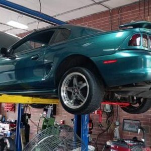
I have had a bit of a tuning problem in that the only local dyno's close have mixed reputations and I can't really travel all that well to go the 3.5-4+ hrs with the car on a trailer to the nearest reputable one. I have also already had 3 tunes done on it up to this point and know I am not done with it, so at what point is it cheaper to get one of the modern self tuning systems and some research/learning on my own that could help solve these problems. After looking at a couple of different systems I went with Holley as they are only about 90 miles away and have good support online as well as classes I am signed up for to go learn more about it. I am not saying this system is for everyone or that it is plug and play. Its taken me a good bit of time tracing wires in the OEM wiring manual(the orange mustang bible) and on their site to figure out what I needed to change, what I could keep, and the options I want to hook up to it. Hopefully this page will help anyone later that installs one but be sure to double check all the info I give, test every wire before you hook it up and don't blame me or this site for any screw ups.:angel:
I am going to do this one a little different and come back and update this first post as I add to it rather then just stick others on under it either before or after any replies in the hope that when its done it will be easier to follow all in one place. If you don't get overwelmed by it all you are a better man then me so hopefully with it all in one place it will make it a little easier. Feel free to ask questions and maybe when I am done and have everything figured out it can be a simple one day install for someone else as its take me a bit longer to get the parts/pieces needed and do all the research I needed as there have been a few times I have been left scratching my head in this process.
First I ordered the system from Holley with a ford wiring ignition harness system.
https://www.holley.com/products/fue...ion/hp_efi/ecu_and_harness_kits/parts/550-606
The TFI(thin film ignition) modules in our 94s are located off board the distributor on the passenger fender. Its easier to use a fox body dist that has the TFI mounted to it.
https://www.holley.com/products/fue...ion/hp_efi/ecu_and_harness_kits/parts/550-606
Aaaaaaaaaaaaaand anyone want to buy a stock 94 dist pm me")
the ford kit was ordered I still needed the ford ignition harness from holley
https://www.holley.com/products/fuel_systems/fuel_injection/hp_efi/hp_harnesses/parts/558-305
other parts I ordered were a small relay/fuse dist block. not sure how long the link to the ebay add will work but here is where I got it. You might want more or less relays/fuses depending one what you are doing. The HP system has 4 programmable outputs that will need relays for of the uses for them. Not sure how long the link to the add will stay up but
]http://www.ebay.com/itm/111735938159?_trksid=p2057872.m2749.l2649&ssPageName=STRK%3AMEBIDX%3AIT
I also had 3 power dist blocks from my install days I will be using for constant power, switched and ground to help make wiring easier.
Fox body dist - The TFI is included in the fox body version were on the sn it is mounted to the passenger fender. The ford ignition harness plugs directly into the fox dist and makes things easier. If you keep the sn TFI you will need to find a place to mount it or rerun some wiring to/from it.
parts to find/modify:
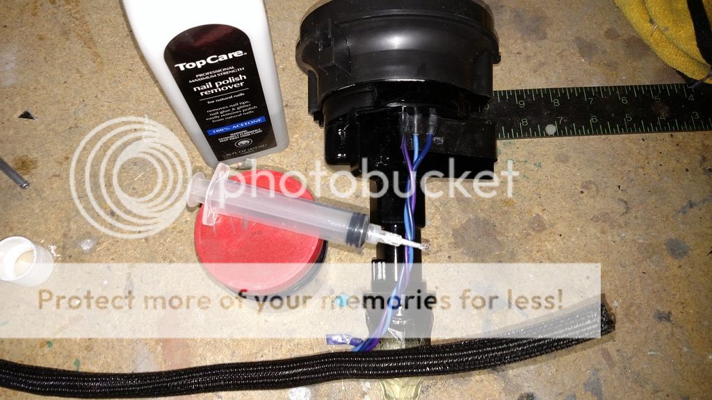
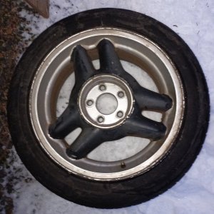
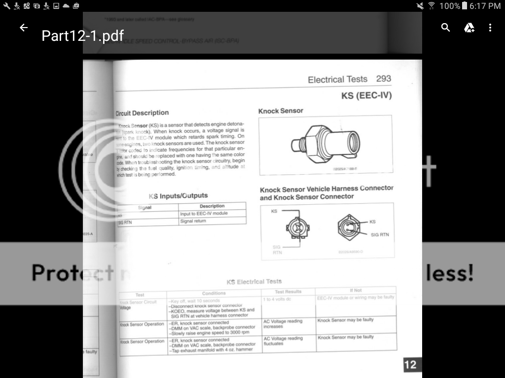
The efi system rather then using a MAF uses a MAP and a knock sensor(anyone wanting to buy a lightning MAF pm me). No big deal to swap out the maf for the map(spare me your opinion on the differences as it seems anytime I mention this to anyone I get to hear their opinion on the two) but the knock sensor for a ford has turned out to be a bit of a unicorn. All the research I found said that a knock sensor from a 96 bronco with the 302 would work and there is a boss drilled/tapped at the back of the block for it but finding the sensor was a challenge. If you ask at your local autoparts store they will do the seach and the system acts like it never existed as ford/lincoln/merc phased them out long ago and the suppliers for them have even seem to quit. I was finally able to locate it on a ebay search, out of china....... I am not sure how many gov watch lists I got on ordering it but it was 1/3 the price of any at the local stores, just took 2.5 weeks to get here.
Knock (Detonation) Sensor For Ford Lincoln 94DA12A699AA F3LY12A699A 2132284
[FONT=&]You can get by with out the sensor but I am running a meth kit with the super charger and would like it to help prevent problems, and its made to use it anyway and the wires are ran. After the searches online and locally to find it and the wait I was excited to see it fit, and then realized I had a whole new problem in finding a harness to plug into it. After searching again I found a close replacement at the local store that ended up fitting after a slight modification to it.
[/FONT]
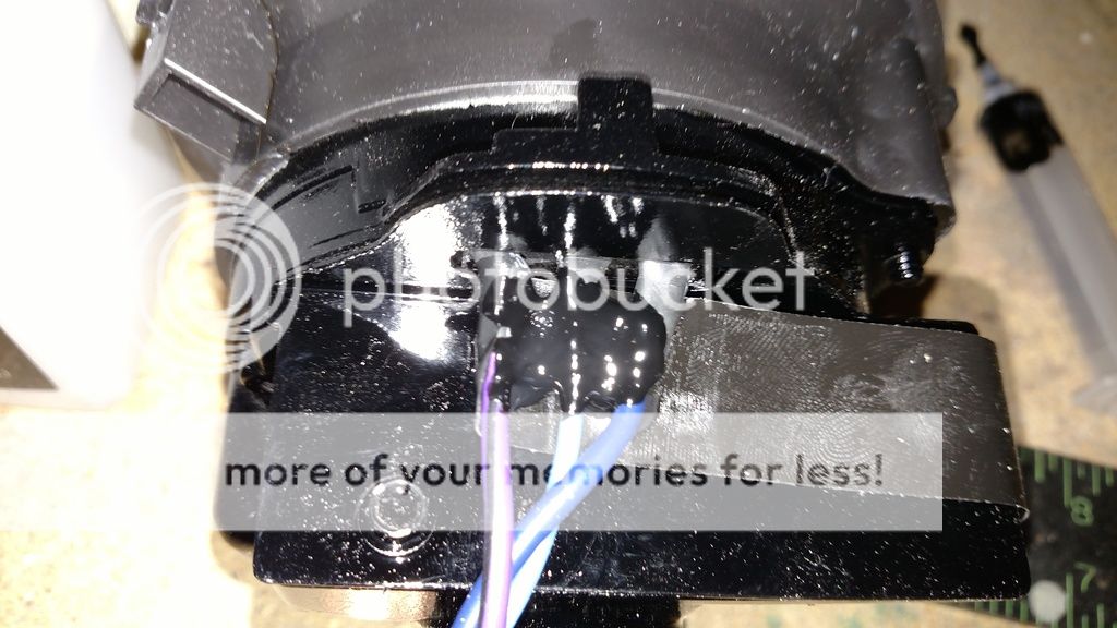
[FONT=&]The knock sensor is on the right, the harness on the left and that is the box the harness came in from oreily's. The difference was that the sensor has 2 locking fins and 1 extra fin that aligned it in a slot. I modified the harness with a cutting wheel on my dremel by adding the slot on the side of the harness and now it will ensure its correctly aligned when it is put in.
[/FONT]
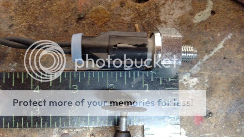
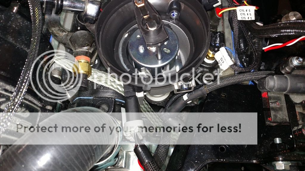
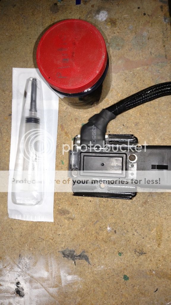
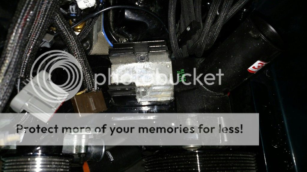
the 302 has a boss drilled/tapped for a knock sensor on the back of the block, behind the lower intake and pcv valve. I screwed it in and the harness I modified now is ready to go.
http://i260.photobucket.com/albums/ii40/ttocsinin/IMG_20161130_152016450.jpg
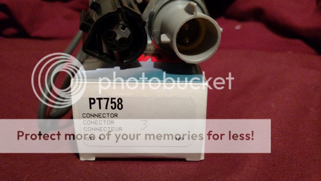
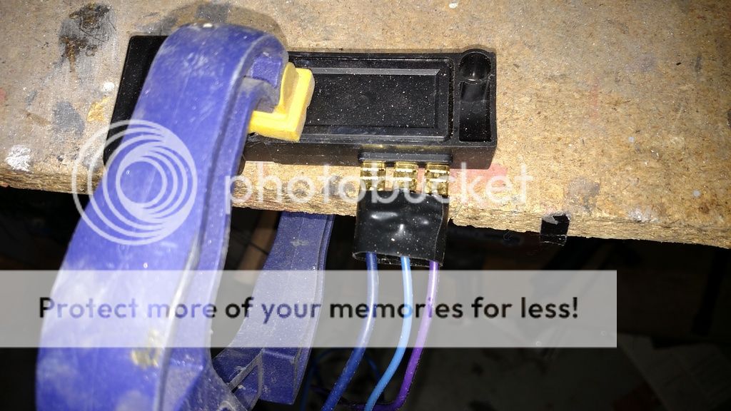
Here is the pin-out of the knock sensor
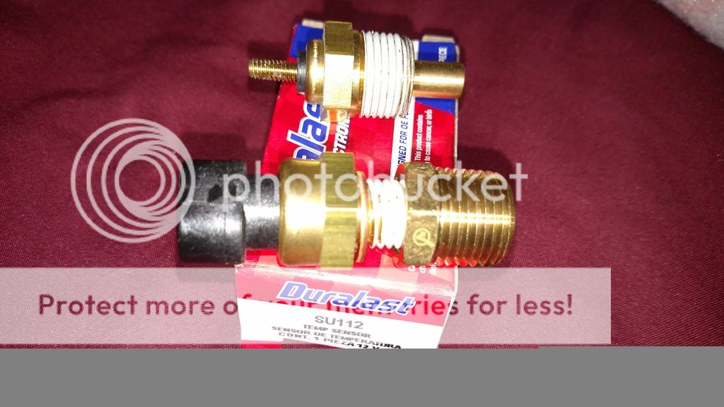
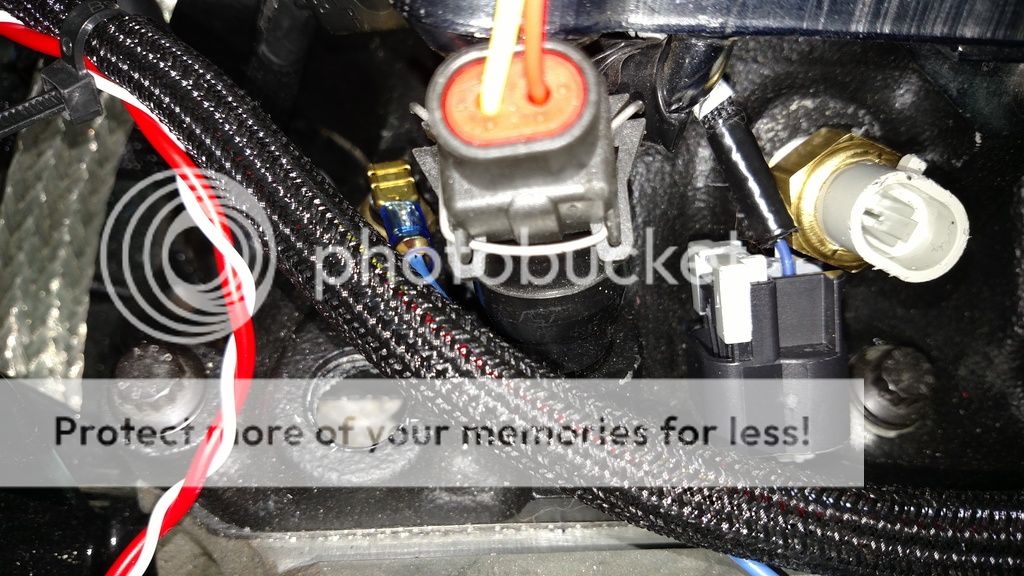
Coolant temp sensor - This is not included in the kit but is the model number on the box from a local auto parts store. Its a sensor from a 2015 gm truck and you also need a 3/8"npt to 1/4" npt adapter that I found at my local hardware store.
the map sensor is included and just needs a vac line to the intake manifold. I will mount this to the firewall and it will not be seen(pic included later).[FONT=&]
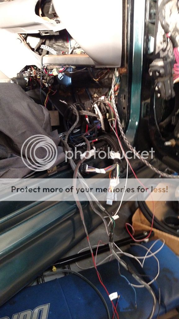
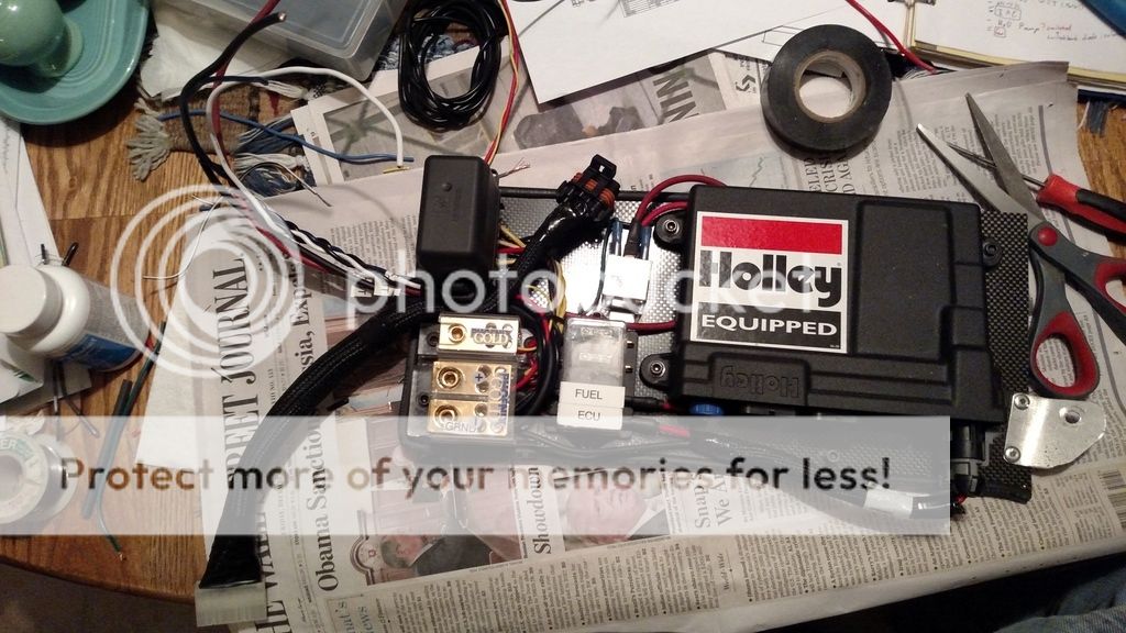
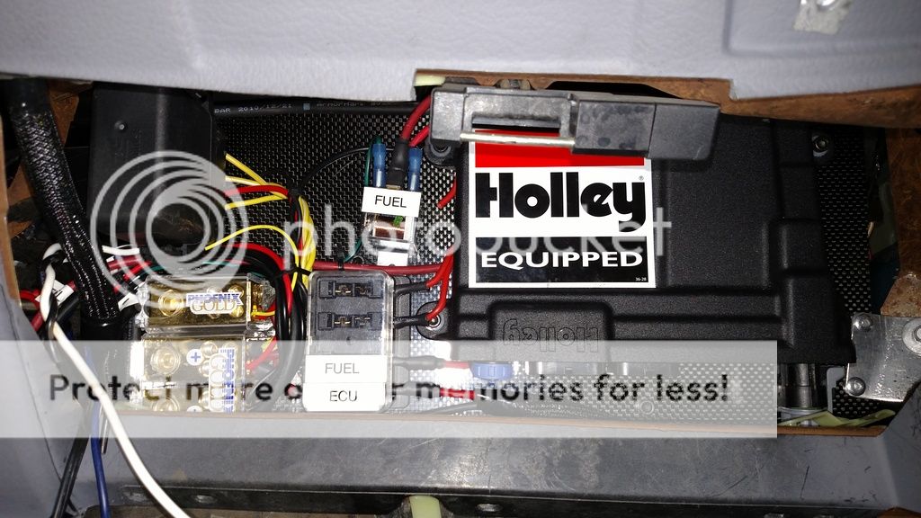
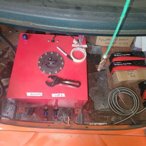
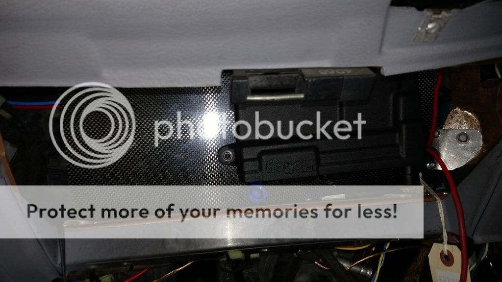
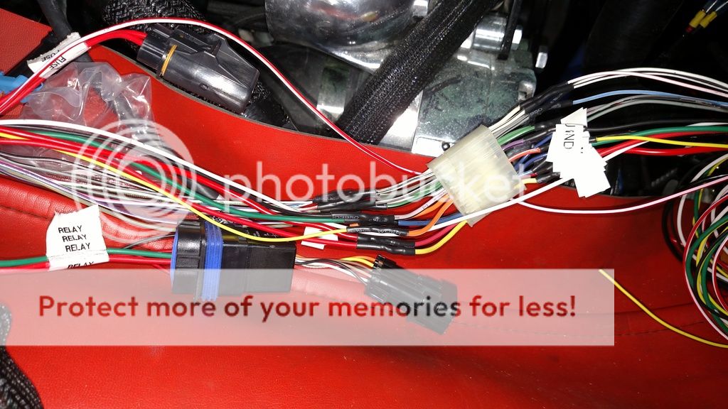
The first thing I would recomend doing is find a place you want to mount it. It is safe to mount in the engine bay but not mounted to your headers. This system completely replaces the stock ecu so you can put it there if you want but I have always hated digging it out behind the wiring in the passenger kick. After some thought I realized after 20 yrs in the car I have never put a pair of gloves in the glove box and with some modifications I could fit this and the manual, the only thing I ever kept in it. I made a plate to mount it, the fuse/relay box and some other crap too and mounted the new ecu to it with rivnuts and machine screws.
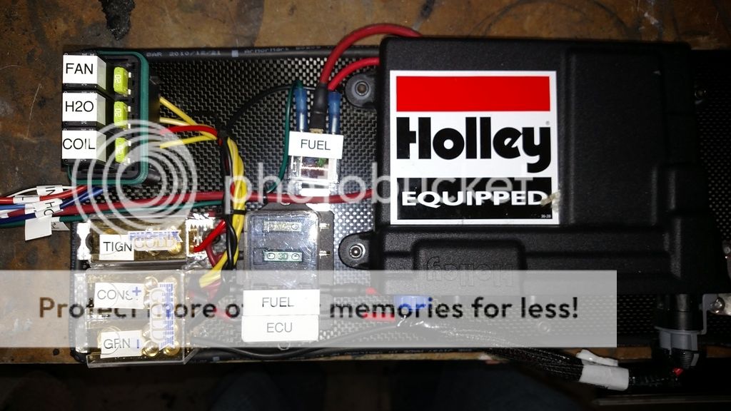
I thought I would have plenty of space for a few dist blocks, a few relays and fuses but the space on the panel quickly filled up. The micro relays up top are rated for 20 amps each which is plenty for everything I have to power such as the water pump, coil and fan. I still have 2 fuses open as well as a little more space if I needed any more relays but hopefully that is all I will need. The hp system came with 12 gauge wires as it has a 40 amp fuse inline. I cut the power wires and ran them through the fuse box to the dist blocks and from there I have the 8 awg power wire below that I will run to my power dist point as well as to a true ignition wire in the ignition harness to power the dist blocks. The larger 8 awg wire will allow the extra possibly 60-80 amps(worst case) that the coil, water pump, fan, and fuel pump could draw as well as the power the holley system to have plenty of volts and amps.
[/FONT]
 [FONT=&]
Manifold air temp - The HP system included a sensor for this that it plugs directly into and it fit the spot I drilled/tapped in the lower intake. The stock location is in the fender, I moved mine here so that the sensor is downstream from the meth nozzle so the temp change will be noticed if it is or is not there. There is a boss there for this that the fox body used and the new sensor fits the old one. The boss is on the drivers side front of the lower intake in between the first two injectors. You do not need to move it but if you keep it in the fender you will need to extend the wires to get to it.
[/FONT]
 [FONT=&]
[/FONT][FONT=&]
Wiring changes before install
I had to make changes to the wire harness. Oddly enough the ford wiring kit comes with mainly gm connectors on it so I am going to be cutting the ends off my stock harness and soldering them on, switching some wires and moving/adding some.
1.)Idle air control - It comes with 4 wires going out to the end of the gm harness. You can keep the harness on it by adding a LSx IAT if you buy a $50 billet mount for it and buy the IAT. After reading in their online support it says the Ford system is actually a better system that reacts faster and moves more air so I find it ironic to make changes to the ford wiring kit to fit a ford part but idunno. From what I found we are not going to use any of the 4 wires that they have in the harness(originally) and need 2 wires for the Ford system. Rather then run two new wires and leave 4 dead ones to bury I opened up the harness just inside the area closest to the ECU now and cut two of the original wires(purple/yellow and purple/black were the two I selected). I insulated the unused ends so they will not short out and then ran the other two ends to come out by my relay/dist block area. The programable input/output wires terminate at a harness there as well as a couple off others so I pulled those ends up to this point. I connected the purple/yellow to the grey/red programmable output and the purple/black to a black wire I will run to the ground dist block and then program this output to run the IAT.
2.) The constant/switched/ground/fuel pump come out of the harness at a slightly higher location then the inputs/outputs so I moved them down to connect to my panel I am making.
3.) I had to run a switched wire for the coil. I think they left this off thinking most people will go COP, which I am not so I added a red 14 gauge wire and ran it with the white tach wire that comes off the TFI wiring kit from the dist to the coil.
4.)input/output harness - there are 4 inputs and 4 outputs that you can program to do darn near anything with and it would be expected that anyone buying this system would use them. So why the hell they do not include the harness to plug into them, and then have the balls to ask $65 for the harness to plug into it?! F-that I was a pack rat of an audio/security installer so I only had to dig through my junk drawer to find a male/female 12-pin harness so I cut theirs off, soldered mine in and then even soldered the matching wires back on the other end so the wiring schematic will still match. It is obviously not a waterproof harness but it will be inside the car, don't matter. The extra pins I was able to use for the switched wires for the coil as well as the fuel pump output so that later on if I need to I can disconnect all the wires and pull the panel down if I need too.
[/FONT]
[FONT=&]IAC - You might think that ordering the ford wiring kit might mean you could plug this in. Wrong... For some reason a GM LSX 4 wire harness is on the end and if you want to keep it plug/play you will need to buy a $60 billet adapter and then the valve on top of that. reading on their forum it is funny to hear them say that the ford system is actually better with a 2 wire system that reacts faster and moves more air so why I would want to pay the extra for the GM is beyond me as well as to again ford kit with GM parts.... They have instructions on their forum how you can use one of the programmable outputs to run a PWM IAC. Rather then run 2 new wires and leave 4 dead, I opened up the harness and cut two of the wires going to the IAC(purple and yellow/purple and black and rewired one to go to one of the programmable outputs, the other goes to the ground wire in the harness.
Wiring I ran
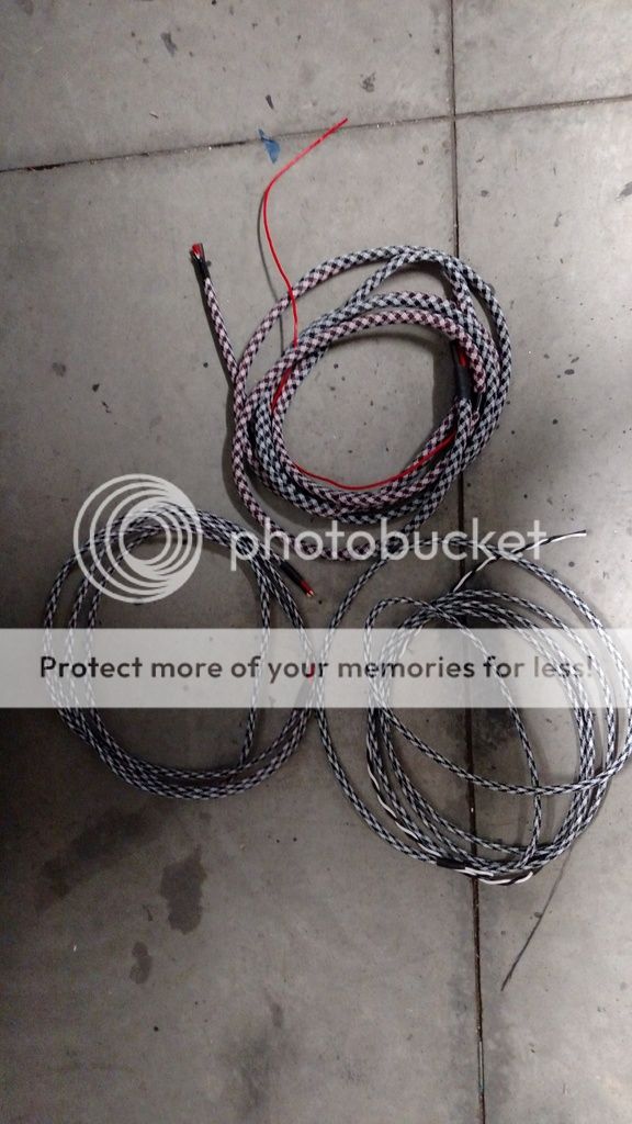
Depending on how you have your system set up you will need to run some wiring. First and what everyone will need to run is a power/ground wire for the system. It comes with 12 awg wiring and a 40 amps inline fuse that will need to go to a 12v constant power source. I cut the 12 awg wire and connected it to my dist blocks, and then ran an 8 awg power/ground to allow the relays that power the water pump, coil, fan and fuel pump to have enough current as well as for the ECU. The wire bundle on the top is the power wires as well as a smaller red 14 awg that will go to a true ignition wire in the ignition harness. The wire bundle to the lower right is 14 gauge wires to power the fan, and on the right the red/black is the original power wires that I am now running to the fuel pump. I wrapped these in the loud checkered tech flex so that I can easily identify which wires are what later.
[/FONT]
New addition dec 28:
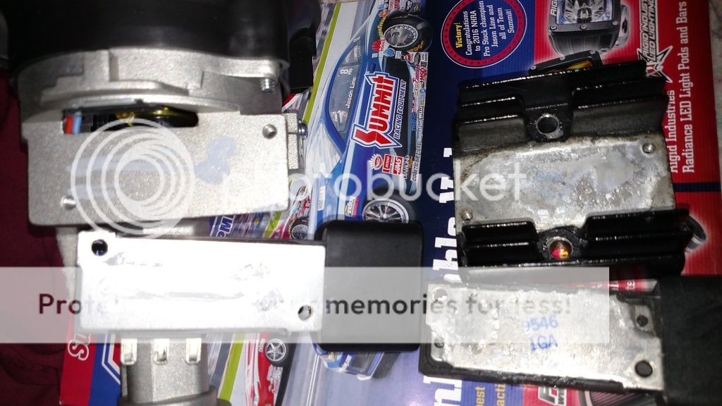
[FONT=&]in addition to power wires there is a small modification needed for the ignition system. The problem is that our 94/95 have the TFI module off of the distributor which in all honesty is better because of heat and the heat sink that ours has mounted to it. We will start by removing the TFI from the alt on the stock fox body alt I mentioned earlier. The TFI sticks out and hits our accessory bracket so we are going to move it. Its held on by 2 5/32 screws but you need either a very thin walled ratched bit ,the special tool for it, or I found that a nut driver was thin enough as well to get them out. Once it is out you pull it down to get the 3 spade connections to slide out and those are the wires we will need to run from the dist to the TFI module. Another VERY important part to this heat sinks equation is a special heat transfer paste that goes between the two. One the old stock 94 piece you can see the paste has long since dried up but that it did cover every inch of the heat sink that touched the module. If you look on the new piece you can see where they drizzled a little bit of the cream but nowhere near enough. I have to wonder how well that ignition module will last since its mounts to a VERY hot part of the motor, has not heat sink to transfer its heat to and then no cream as well.
[/FONT]
[FONT=&]You will need to use male/female spade connectors to connect to the terminals and of course its important to make sure you get them matched up correctly. I am trying to make a harness here by pouring some liquid abs between the spade connectors and then after it dries I will put a piece of heat shrink over it. I will let you know if that works...
[/FONT]
You also need to modify the heat sink by cutting the fins off where the wires will be ran. I am mounting it under the coil by making a new bracket that will hold the coil up a couple of inches to clear the TFI module below it.
[FONT=&]there is an open spot on the dist that needs to be covered to prevent dirt/water from getting in so I made a cover for it.
[/FONT]
[FONT=&]Now its just a matter of running those 3 wires from the dist to the TFI module. I do not have the male spades I need at the moment so the finished pic will have to wait.
[/FONT][FONT=&]
staythirstymyfriends.....[/FONT]
I am going to do this one a little different and come back and update this first post as I add to it rather then just stick others on under it either before or after any replies in the hope that when its done it will be easier to follow all in one place. If you don't get overwelmed by it all you are a better man then me so hopefully with it all in one place it will make it a little easier. Feel free to ask questions and maybe when I am done and have everything figured out it can be a simple one day install for someone else as its take me a bit longer to get the parts/pieces needed and do all the research I needed as there have been a few times I have been left scratching my head in this process.
First I ordered the system from Holley with a ford wiring ignition harness system.
https://www.holley.com/products/fue...ion/hp_efi/ecu_and_harness_kits/parts/550-606
The TFI(thin film ignition) modules in our 94s are located off board the distributor on the passenger fender. Its easier to use a fox body dist that has the TFI mounted to it.
https://www.holley.com/products/fue...ion/hp_efi/ecu_and_harness_kits/parts/550-606
Aaaaaaaaaaaaaand anyone want to buy a stock 94 dist pm me
the ford kit was ordered I still needed the ford ignition harness from holley
https://www.holley.com/products/fuel_systems/fuel_injection/hp_efi/hp_harnesses/parts/558-305
other parts I ordered were a small relay/fuse dist block. not sure how long the link to the ebay add will work but here is where I got it. You might want more or less relays/fuses depending one what you are doing. The HP system has 4 programmable outputs that will need relays for of the uses for them. Not sure how long the link to the add will stay up but
]http://www.ebay.com/itm/111735938159?_trksid=p2057872.m2749.l2649&ssPageName=STRK%3AMEBIDX%3AIT
I also had 3 power dist blocks from my install days I will be using for constant power, switched and ground to help make wiring easier.
Fox body dist - The TFI is included in the fox body version were on the sn it is mounted to the passenger fender. The ford ignition harness plugs directly into the fox dist and makes things easier. If you keep the sn TFI you will need to find a place to mount it or rerun some wiring to/from it.
parts to find/modify:
The efi system rather then using a MAF uses a MAP and a knock sensor(anyone wanting to buy a lightning MAF pm me
). No big deal to swap out the maf for the map(spare me your opinion on the differences as it seems anytime I mention this to anyone I get to hear their opinion on the two) but the knock sensor for a ford has turned out to be a bit of a unicorn. All the research I found said that a knock sensor from a 96 bronco with the 302 would work and there is a boss drilled/tapped at the back of the block for it but finding the sensor was a challenge. If you ask at your local autoparts store they will do the seach and the system acts like it never existed as ford/lincoln/merc phased them out long ago and the suppliers for them have even seem to quit. I was finally able to locate it on a ebay search, out of china....... I am not sure how many gov watch lists I got on ordering it but it was 1/3 the price of any at the local stores, just took 2.5 weeks to get here.Knock (Detonation) Sensor For Ford Lincoln 94DA12A699AA F3LY12A699A 2132284
[FONT=&]You can get by with out the sensor but I am running a meth kit with the super charger and would like it to help prevent problems, and its made to use it anyway and the wires are ran. After the searches online and locally to find it and the wait I was excited to see it fit, and then realized I had a whole new problem in finding a harness to plug into it. After searching again I found a close replacement at the local store that ended up fitting after a slight modification to it.
[/FONT]
[FONT=&]The knock sensor is on the right, the harness on the left and that is the box the harness came in from oreily's. The difference was that the sensor has 2 locking fins and 1 extra fin that aligned it in a slot. I modified the harness with a cutting wheel on my dremel by adding the slot on the side of the harness and now it will ensure its correctly aligned when it is put in.
[/FONT]
the 302 has a boss drilled/tapped for a knock sensor on the back of the block, behind the lower intake and pcv valve. I screwed it in and the harness I modified now is ready to go.
http://i260.photobucket.com/albums/ii40/ttocsinin/IMG_20161130_152016450.jpg
Here is the pin-out of the knock sensor
Coolant temp sensor - This is not included in the kit but is the model number on the box from a local auto parts store. Its a sensor from a 2015 gm truck and you also need a 3/8"npt to 1/4" npt adapter that I found at my local hardware store.
the map sensor is included and just needs a vac line to the intake manifold. I will mount this to the firewall and it will not be seen(pic included later).[FONT=&]
The first thing I would recomend doing is find a place you want to mount it. It is safe to mount in the engine bay but not mounted to your headers. This system completely replaces the stock ecu so you can put it there if you want but I have always hated digging it out behind the wiring in the passenger kick. After some thought I realized after 20 yrs in the car I have never put a pair of gloves in the glove box and with some modifications I could fit this and the manual, the only thing I ever kept in it. I made a plate to mount it, the fuse/relay box and some other crap too and mounted the new ecu to it with rivnuts and machine screws.
I thought I would have plenty of space for a few dist blocks, a few relays and fuses but the space on the panel quickly filled up. The micro relays up top are rated for 20 amps each which is plenty for everything I have to power such as the water pump, coil and fan. I still have 2 fuses open as well as a little more space if I needed any more relays but hopefully that is all I will need. The hp system came with 12 gauge wires as it has a 40 amp fuse inline. I cut the power wires and ran them through the fuse box to the dist blocks and from there I have the 8 awg power wire below that I will run to my power dist point as well as to a true ignition wire in the ignition harness to power the dist blocks. The larger 8 awg wire will allow the extra possibly 60-80 amps(worst case) that the coil, water pump, fan, and fuel pump could draw as well as the power the holley system to have plenty of volts and amps.
[/FONT]
Manifold air temp - The HP system included a sensor for this that it plugs directly into and it fit the spot I drilled/tapped in the lower intake. The stock location is in the fender, I moved mine here so that the sensor is downstream from the meth nozzle so the temp change will be noticed if it is or is not there. There is a boss there for this that the fox body used and the new sensor fits the old one. The boss is on the drivers side front of the lower intake in between the first two injectors. You do not need to move it but if you keep it in the fender you will need to extend the wires to get to it.
[/FONT]
[/FONT][FONT=&]
Wiring changes before install
I had to make changes to the wire harness. Oddly enough the ford wiring kit comes with mainly gm connectors on it so I am going to be cutting the ends off my stock harness and soldering them on, switching some wires and moving/adding some.
1.)Idle air control - It comes with 4 wires going out to the end of the gm harness. You can keep the harness on it by adding a LSx IAT if you buy a $50 billet mount for it and buy the IAT. After reading in their online support it says the Ford system is actually a better system that reacts faster and moves more air so I find it ironic to make changes to the ford wiring kit to fit a ford part but idunno. From what I found we are not going to use any of the 4 wires that they have in the harness(originally) and need 2 wires for the Ford system. Rather then run two new wires and leave 4 dead ones to bury I opened up the harness just inside the area closest to the ECU now and cut two of the original wires(purple/yellow and purple/black were the two I selected). I insulated the unused ends so they will not short out and then ran the other two ends to come out by my relay/dist block area. The programable input/output wires terminate at a harness there as well as a couple off others so I pulled those ends up to this point. I connected the purple/yellow to the grey/red programmable output and the purple/black to a black wire I will run to the ground dist block and then program this output to run the IAT.
2.) The constant/switched/ground/fuel pump come out of the harness at a slightly higher location then the inputs/outputs so I moved them down to connect to my panel I am making.
3.) I had to run a switched wire for the coil. I think they left this off thinking most people will go COP, which I am not so I added a red 14 gauge wire and ran it with the white tach wire that comes off the TFI wiring kit from the dist to the coil.
4.)input/output harness - there are 4 inputs and 4 outputs that you can program to do darn near anything with and it would be expected that anyone buying this system would use them. So why the hell they do not include the harness to plug into them, and then have the balls to ask $65 for the harness to plug into it?! F-that I was a pack rat of an audio/security installer so I only had to dig through my junk drawer to find a male/female 12-pin harness so I cut theirs off, soldered mine in and then even soldered the matching wires back on the other end so the wiring schematic will still match. It is obviously not a waterproof harness but it will be inside the car, don't matter. The extra pins I was able to use for the switched wires for the coil as well as the fuel pump output so that later on if I need to I can disconnect all the wires and pull the panel down if I need too.
[/FONT]
[FONT=&]IAC - You might think that ordering the ford wiring kit might mean you could plug this in. Wrong... For some reason a GM LSX 4 wire harness is on the end and if you want to keep it plug/play you will need to buy a $60 billet adapter and then the valve on top of that. reading on their forum it is funny to hear them say that the ford system is actually better with a 2 wire system that reacts faster and moves more air so why I would want to pay the extra for the GM is beyond me as well as to again ford kit with GM parts.... They have instructions on their forum how you can use one of the programmable outputs to run a PWM IAC. Rather then run 2 new wires and leave 4 dead, I opened up the harness and cut two of the wires going to the IAC(purple and yellow/purple and black and rewired one to go to one of the programmable outputs, the other goes to the ground wire in the harness.
Wiring I ran
Depending on how you have your system set up you will need to run some wiring. First and what everyone will need to run is a power/ground wire for the system. It comes with 12 awg wiring and a 40 amps inline fuse that will need to go to a 12v constant power source. I cut the 12 awg wire and connected it to my dist blocks, and then ran an 8 awg power/ground to allow the relays that power the water pump, coil, fan and fuel pump to have enough current as well as for the ECU. The wire bundle on the top is the power wires as well as a smaller red 14 awg that will go to a true ignition wire in the ignition harness. The wire bundle to the lower right is 14 gauge wires to power the fan, and on the right the red/black is the original power wires that I am now running to the fuel pump. I wrapped these in the loud checkered tech flex so that I can easily identify which wires are what later.
[/FONT]
New addition dec 28:
[FONT=&]in addition to power wires there is a small modification needed for the ignition system. The problem is that our 94/95 have the TFI module off of the distributor which in all honesty is better because of heat and the heat sink that ours has mounted to it. We will start by removing the TFI from the alt on the stock fox body alt I mentioned earlier. The TFI sticks out and hits our accessory bracket so we are going to move it. Its held on by 2 5/32 screws but you need either a very thin walled ratched bit ,the special tool for it, or I found that a nut driver was thin enough as well to get them out. Once it is out you pull it down to get the 3 spade connections to slide out and those are the wires we will need to run from the dist to the TFI module. Another VERY important part to this heat sinks equation is a special heat transfer paste that goes between the two. One the old stock 94 piece you can see the paste has long since dried up but that it did cover every inch of the heat sink that touched the module. If you look on the new piece you can see where they drizzled a little bit of the cream but nowhere near enough. I have to wonder how well that ignition module will last since its mounts to a VERY hot part of the motor, has not heat sink to transfer its heat to and then no cream as well.
[/FONT]
[FONT=&]You will need to use male/female spade connectors to connect to the terminals and of course its important to make sure you get them matched up correctly. I am trying to make a harness here by pouring some liquid abs between the spade connectors and then after it dries I will put a piece of heat shrink over it. I will let you know if that works...
[/FONT]
You also need to modify the heat sink by cutting the fins off where the wires will be ran. I am mounting it under the coil by making a new bracket that will hold the coil up a couple of inches to clear the TFI module below it.
[FONT=&]there is an open spot on the dist that needs to be covered to prevent dirt/water from getting in so I made a cover for it.
[/FONT]
[FONT=&]Now its just a matter of running those 3 wires from the dist to the TFI module. I do not have the male spades I need at the moment so the finished pic will have to wait.
[/FONT][FONT=&]
staythirstymyfriends.....[/FONT]