OP
OP
Wow, very cool. Not something I will be personally doing, but I enjoyed the read and learned a few things.
Thank you for taking the time to make this thread.
Thanks! Still not done with it, got a few things to wrap up
")
Wow, very cool. Not something I will be personally doing, but I enjoyed the read and learned a few things.
Thank you for taking the time to make this thread.
Wow, really a comprehensive writeup. A lot of work and documentation with great pics and diagrams.
mcglsr2 how does that bezel attach to the dash? It looks like it might need to be screwed in? Also, do you think all of the gauges will be visible if you were to install a column pod with the one gauge off to the right hand side?
I ask so many questions because I am getting ready to do this. Thank you for this write up, its been very helpful so far and ill be using it in the near future.
OMG I TOTALLY FORGOT ABOUT THIS THREAD! I need to finish updating it. Everything is pretty much done. Over the next couple days I will wrap this guy up. Thanks for reminding me of it!
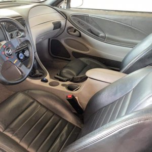
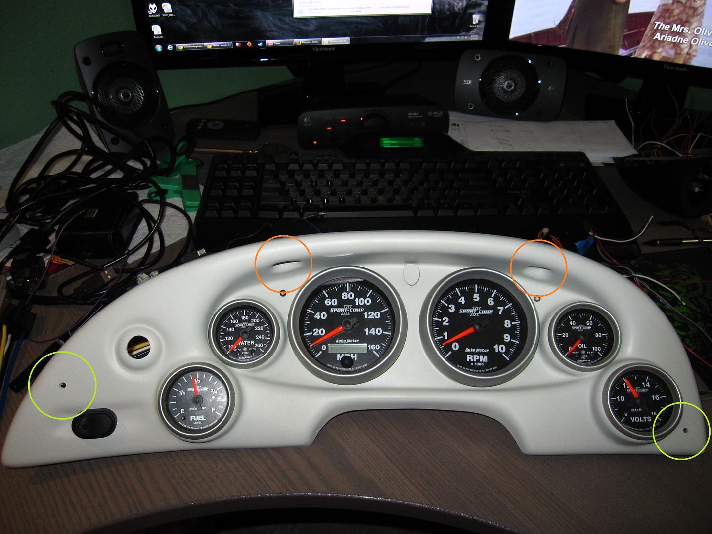
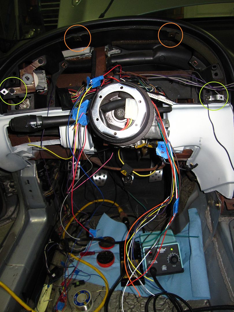
Now, to your questions: the bezel attaches at 4 points. The top uses the stock screws in the stock screw holes. So that one is super easy. The other two attachment points are at the lower left, and lower right. The bezel will come with two aluminum brackets, you will screw the brackets in to existing holes using existing screws. The bracket will then attach to the bezel using smaller screws that are provided with the bezel. I'll see if I can find some images that show this better. The hardest part (and the whole thing is pretty easy) is making sure the brackets line up with the holes in the bezel. A couple trial fits before populating the bezel with gauges is all it will take.
As to the column pod - not sure. The way I have my gauges arranged, that may block some of the tach and some of the oil pressure. But there's like a gap there between those gauges, so it may not actually block any of it. You can also arrange gauges however you want: for example, a pretty common thing done is to clock the tach so that when the needle hits your shift RPM, it's pointing straight up. This makes it easier to see that you are at shift RPM, as you can more quickly interpret the position of the needle rather than the number it is pointing to. (In my cause, I use a shift light, so I clocked the tach normal.) So you can do things like that to make sure the relevant information is still visible even if the column pod blocks a little.
Youre welcome, and thank you lol. Ive been watching this thread since the beginning so I dont forget it. Thanks for the info and If its not too much hassle I would really appreciate a couple pictures of the attachment points. I can pretty well visualize it but photos always help.
That did it. I wasnt following along with the lower attachments. I saw the little brackets and it all clicked. Ill have plenty more questions in the future. Thanks a bunch for all the time and effort you put into this.
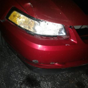
HUGE depressing moment earlier...................I dropped my speedometer and put a dent in the ring, I havent been this depressed in a long time.
mcglsr2, I have more dumb questions.
What led's did you use for the left turn, right turn, and high beam?
How did you attach them to the panel? I remember you made the cover for the high beam led, what is that made of and how did you attach it? My panel is due here probably tomorrow so I am about to start on this portion of the project.