ttocs
Post Whore
I see a lot of people that as soon as you mention they need a relay that they act like it is some HUGE amount of work. I think its mainly just the unknown that people have not taken a few seconds to see what they are, and how they work. When you do its not a big deal to throw one in when its needed. Saying that now of course I need to put some kind of warning that protects me and the site from screw ups. Don't screw it up or bad stuff can happen and its not my or the sites fault. OK?!
So first take the relay out and look at it. The pic on the top shows everything you need to know.
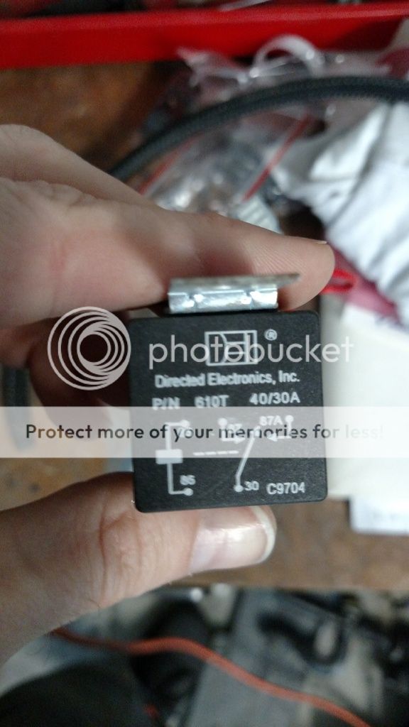
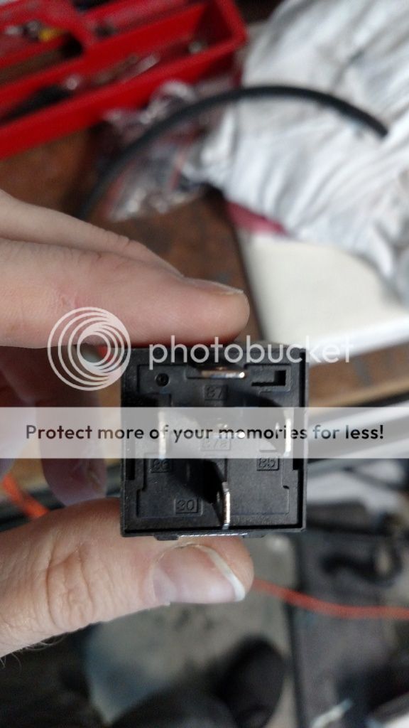
There are two parts to a relay. There is the coil that makes up the electromagnet, and there is the switch. The coil is shown on the left in between 85 and 86, and the switch is on the right between 87a, 87, 86. The magnet is what we use to activate or move the switch but there are connections on the switch that allow for it to be used in a couple of ways that I will show later. I don't know who choose those numbers or why they picked what they did but that is not important, just accept it... Pins 85 and 86 go to the coil/magnet. When you put +12v on one, and -12v on the other you will hear the relay click as the relays coil activates and moves the switch. Now it does not matter which way is +- on the coil, just that 12v on it makes it move. The switch can also be hooked up any way you want as it is not polarized meaning it has a +/-. Before the coil is activated the contacts 87a/30 are connected which is shown in the schematic on the relay. This allows for things to be turned off when the coil is activated. Before the coil is activated pins 30/87 are not connected, but are when the coil is on. The real problem I think that confuses people is that they do not know what the pins on the bottom are but if you look next to each pin you will see a small number printed on the relay.
to connect to the relay I use insulated female spade connectors. The simply crimp onto the wire and then slide onto the pin and I will show you how to make a fuse holder out of them later.
The most common use for a relay is when more current is needed. A perfect example is I upgraded my fuel pump but unless the wiring can handle the current that the pump can create, you have not upgraded all that much and might have created a hazard since the wiring can get hot and melt... Again lets break the relay down to its two parts, the coil and the switch and then we can wire it First we need to activate the coil/magnet and that is done easily with the power that is normaly fed into the fuel pump. I simply cut the wires, crimped my connectors on it and that goes to 85/86 on the coil. With the coil being non-polarized it doesn't matter +/- so the relay could be flipped around and it will still work the same way.
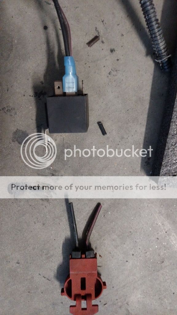
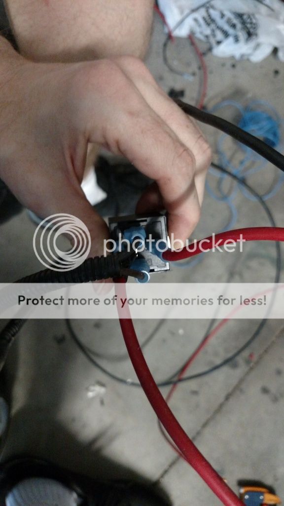
Now that is done we need to worry about the switch and in this situation we want to supply power when the coil is on so we only need to use 2 of the three pins, 87/30. I Normally wire 30 as my output so I connected the new/thicker wire from 30 to where I cut the harness, and 87 now needs to be ran to either a 12v constant source and NEEDS to be fused as close to that source as possible. its the new/thicker wires that will allow the new 340lph fuel pump to get as much current as it needs to be happy. For me my batteries are directly above so it will be a short run but you will notice I am also increasing the ground wire for the pump. If I did not do this, that thinner ground wire would have been the weak link in the chain and it could get hot. This first pic just shows that we did not use the pin in the middle, 87a. That pin you remember is connected to 30 and we are not using that side of the switch. Now because its not used, does not mean its not hot and that pin will be in this case so I put an unused connector over it to insulate it after I took this pic
So first take the relay out and look at it. The pic on the top shows everything you need to know.

There are two parts to a relay. There is the coil that makes up the electromagnet, and there is the switch. The coil is shown on the left in between 85 and 86, and the switch is on the right between 87a, 87, 86. The magnet is what we use to activate or move the switch but there are connections on the switch that allow for it to be used in a couple of ways that I will show later. I don't know who choose those numbers or why they picked what they did but that is not important, just accept it... Pins 85 and 86 go to the coil/magnet. When you put +12v on one, and -12v on the other you will hear the relay click as the relays coil activates and moves the switch. Now it does not matter which way is +- on the coil, just that 12v on it makes it move. The switch can also be hooked up any way you want as it is not polarized meaning it has a +/-. Before the coil is activated the contacts 87a/30 are connected which is shown in the schematic on the relay. This allows for things to be turned off when the coil is activated. Before the coil is activated pins 30/87 are not connected, but are when the coil is on. The real problem I think that confuses people is that they do not know what the pins on the bottom are but if you look next to each pin you will see a small number printed on the relay.

to connect to the relay I use insulated female spade connectors. The simply crimp onto the wire and then slide onto the pin and I will show you how to make a fuse holder out of them later.
The most common use for a relay is when more current is needed. A perfect example is I upgraded my fuel pump but unless the wiring can handle the current that the pump can create, you have not upgraded all that much and might have created a hazard since the wiring can get hot and melt... Again lets break the relay down to its two parts, the coil and the switch and then we can wire it First we need to activate the coil/magnet and that is done easily with the power that is normaly fed into the fuel pump. I simply cut the wires, crimped my connectors on it and that goes to 85/86 on the coil. With the coil being non-polarized it doesn't matter +/- so the relay could be flipped around and it will still work the same way.

Now that is done we need to worry about the switch and in this situation we want to supply power when the coil is on so we only need to use 2 of the three pins, 87/30. I Normally wire 30 as my output so I connected the new/thicker wire from 30 to where I cut the harness, and 87 now needs to be ran to either a 12v constant source and NEEDS to be fused as close to that source as possible. its the new/thicker wires that will allow the new 340lph fuel pump to get as much current as it needs to be happy. For me my batteries are directly above so it will be a short run but you will notice I am also increasing the ground wire for the pump. If I did not do this, that thinner ground wire would have been the weak link in the chain and it could get hot. This first pic just shows that we did not use the pin in the middle, 87a. That pin you remember is connected to 30 and we are not using that side of the switch. Now because its not used, does not mean its not hot and that pin will be in this case so I put an unused connector over it to insulate it after I took this pic


