How to: Installing gauges in 1995 Mustang GT.

maillemaker

Active Member
Joined
Mar 5, 2023
Messages
419
Reaction score
218
This thread will document my installation of Glowshift gauges into my 1995 Mustang GT.

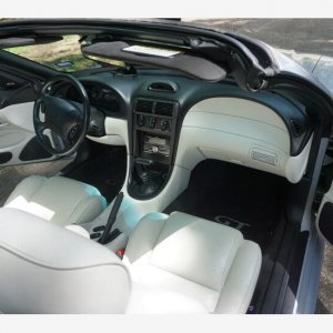
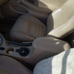
I will be installing GlowShift Dual Temperature, Dual Pressure, and Volts meters. They will be installed in the center console under the radio, where the factory CD holder bin was located.

Parts:
1/8 - 1/16 NPT Adapter
FasParts 3/8" NPT Male NPT MIP MPT x 1/8" NPT Female FIP FPT Reducer Bushing
Permatex 80016 Form-A-Gasket #2 Sealant, 3 oz. , Blue, Non-hardening
Anderson Metals - 06127-02 Brass Pipe Fitting, Barstock Street Tee, 1/8" Female Pipe x 1/8" Male Pipe x 1/8" Female Pipe
Earl's 1/8 Npt Male Schrader Valve
DC-DC Stabilizer
GlowShift 10 Color Digital Volt Voltmeter Gauge
GlowShift 10 Color Digital 300 F Dual Temperature Gauge Kit
GlowShift 10 Color Digital 100 PSI Dual Pressure Gauge Kit
GlowShift Oil Filter Sandwich Plate Thread Adapter
1979-1995 Mustang Thermostat Housing - 5.0/5.8
1994-00 Mustang SVE Radio Bezel - 3 Gauge Panel 2 1/16"
20pcs 2A Standard Car Fuses - 2 AMP Automotive Fuses(ATO/APR/ATS)
Recoil FT1-10 10 Pack 12V Car Add-a-Circuit Fuse Tap Adapter ATO ATC Blade Fuse Holder

IMG_8195.JPG


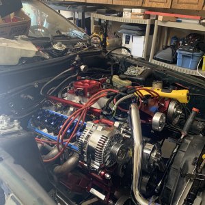
Step 1 - Engine Coolant Sensor Install
The factory thermostat housing actually has a cast-in depression for where a threaded sensor could be put, if it had been drilled and tapped. Unfortunately, on my GT, it had not been.

Instead, I ordered a new thermostat housing from LMR that has a 3/8 NPT threaded port in it.

If I had this to do over again, I would have preferred to drill and tap the Ford housing, because the LMR housing does not accept the correct thermostat - it does not fit properly. However, the pressed-in tube for the heater bypass hose was quite corroded on my OE housing, so I would have had to refurbish or replace it anyway. More on this later.

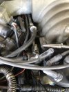
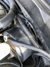
First step is to remove the existing housing. Loosen the hose clamps for the radiator hose and each end of the formed heater hose. Then loosen and remove the two thermostat housing bolts. Beware that they are different lengths. The short one goes on the driver's side.

IMG_8196.JPGIMG_8197.JPGIMG_8198.JPG
IMG_8199.JPG

Next, I got the new housing ready for use. I used a hex wrench to remove the 3/8" NPT plug from the housing. Then I installed the 3/8 - 1/8 NPT Bushing to accept the Glowshift thermal sensor. I put these parts together using the non-hardening Permatex.


IMG_8202.JPG
IMG_8203.JPG
IMG_8210.JPG

Next, I cleaned up the gasket surface with a scraper and some 3M scrubby material.

IMG_8211.JPGIMG_8212.JPG
 
Last edited:
OP
OP
M

maillemaker

Active Member
Joined
Mar 5, 2023
Messages
419
Reaction score
218
Then, with some RTV lightly spread on either side of the gasket, and the thermostat back in place, put it all back together.

IMG_8213.JPG

Unfortunately, there is a problem with the LMR thermostat housing.

I went to the local Ford dealership and got the correct Motorcraft thermostat for my vehicle. It is RT-1139. This thermostat has a brass "stake" embedded in it that alights with a machined-out pocket in the thermostat housing to ensure correct alignment. Further, this thermostat has a shoulder that needs lots of room inside the housing so that the thermostat flange will bottom out in its machined seat. The LMR casting has shoulders that rise up too high inside the housing, so the correct thermostat will not sit flush as it should. The first time I put it all back together and fired up the motor the housing leaked all over because it could not bottom out and seal due to the thermostat not being able to seat properly.

Fortunately the thermostat that I pulled out of the car did not have a locating bead and did not have a shoulder, so it fit fine. I didn't want to re-use the old thermostat but since I was having no thermal issues before, and it fit, I went ahead and used it. To use the correct Motorcraft thermostat I would have to take my Dremel tool to the housing to remove some material so that the thermostat would sit.

If I had to do this over again I'd drill and tap my original housing, or find a NOS one.

shoulder.jpg

More to come...
 
OP
OP
M

maillemaker

Active Member
Joined
Mar 5, 2023
Messages
419
Reaction score
218
Step 2: Oil Pressure Sensor install

Normally I like to install a "T" fitting where the factory oil pressure sensor is, and then put the OE sensor and the new pickup on the T. But the OE oil pressure sending unit is in a tight spot in front of the oil filter, and I'm not sure I could screw the T into place, and if I did, I'm not sure what direction the T would end up pointing so that I could screw in one of the pressure sending units.

So instead, I installed an adapter plate from Glowshift that is a spacer under the oil filter. This spacer is tapped with 1/8" NPT ports for installing multiple sensors if desired. I am only installing a pressure sending unit for the Glowshift gauge.

IMG_8222.JPGIMG_8223.JPG

I went ahead and installed the sending unit into the adapter plate before installing the assembly onto the block.

Attaching to the block is simple.

Just remove the oil filter (have a catch pan ready because some oil will drain out of the filter), and then screw the adapter plate to the block. You'll want a 26mm deep well socket for this. A standard socket will work if you don't engage your wrench 100% into the socket.

IMG_8230.JPG

Then screw the filter onto the adapter plate.
IMG_8231.JPG

As always, whenever you are attaching an oil filter (or the adapter plate) rub some engine oil onto the rubber gasket before installing.
 
OP
OP
M

maillemaker

Active Member
Joined
Mar 5, 2023
Messages
419
Reaction score
218
Step 3: Install the fuel pressure sending unit

The Schrader valve on the fuel rail is easy to access, and threads out of the fuel rail with a deep well socket. Be gentle as you don't want to damage the fuel rail. Be sure to surround the valve with a shop towel and depress the pintle in the valve to bleed off fuel pressure from the rail before attempting to remove it. Fuel can spray out here so wear safety goggles and watch your eyes. Good idea to have a fire extinguisher handy also.

IMG_8226.JPG
IMG_8227.JPG

I wanted to preserve the functionality of the Schrader valve so that I could relieve pressure in the rail if needed, or hook up an external fuel pressure gauge if needed.

So, I installed a "T" fitting that allowed me to have a Schrader valve and the pressure sending unit.

The OE valve is 1/16" NPT, so I used a 1/16 - 1/8" NPT adapter. Then a 1/8" NPT "T" to allow installing the sending unit and a new Schrader valve.


IMG_8224.JPG
IMG_8225.JPG

The fittings were all sealed with Permatex non-hardening thread sealer.

After this, apply some more Permatex to the end that screws into the fuel rail, and snugly, but carefully, tight it down.

IMG_8229.JPG
 

Attachments

  • IMG_8226.JPG
    IMG_8226.JPG
    184.7 KB · Views: 3
OP
OP
M

maillemaker

Active Member
Joined
Mar 5, 2023
Messages
419
Reaction score
218
Step 4: Install the transmission temperature sensor.

This is the easiest sensor to install. Just remove the plug from the test port on the driver's side of the transmission, and replace it with the temperature sending unit. Use the Permatex sealer on the threads.

You'll find a lot of debate on where to install a temperature sensor for an automatic transmission. If you want the absolute hottest reading, and the fastest read, installing it on the exit line as the fluid leaves the transmission is the place. The pan is not a great place to install the sensor, in my opinion, because this is fluid that has been through the transmission cooler and dumped back into the transmission.

You'll find many posts by Mark Kovalsky, a past Ford transmission engineer, on the internet where he says the Test Port is a fine place to put a temperature sensor. So that is what I've done.


IMG_8232.JPG
IMG_8233.JPG
 
OP
OP
M

maillemaker

Active Member
Joined
Mar 5, 2023
Messages
419
Reaction score
218
Make sure nothing leaks
After you have installed all of the sensors, take the car for a short drive and when you get back verify that nothing is leaking.
 

Bogs

New Member
Joined
Jun 28, 2023
Messages
22
Reaction score
5
Then, with some RTV lightly spread on either side of the gasket, and the thermostat back in place, put it all back together.

View attachment 28509

Unfortunately, there is a problem with the LMR thermostat housing.

I went to the local Ford dealership and got the correct Motorcraft thermostat for my vehicle. It is RT-1139. This thermostat has a brass "stake" embedded in it that alights with a machined-out pocket in the thermostat housing to ensure correct alignment. Further, this thermostat has a shoulder that needs lots of room inside the housing so that the thermostat flange will bottom out in its machined seat. The LMR casting has shoulders that rise up too high inside the housing, so the correct thermostat will not sit flush as it should. The first time I put it all back together and fired up the motor the housing leaked all over because it could not bottom out and seal due to the thermostat not being able to seat properly.

Fortunately the thermostat that I pulled out of the car did not have a locating bead and did not have a shoulder, so it fit fine. I didn't want to re-use the old thermostat but since I was having no thermal issues before, and it fit, I went ahead and used it. To use the correct Motorcraft thermostat I would have to take my Dremel tool to the housing to remove some material so that the thermostat would sit.

If I had to do this over again I'd drill and tap my original housing, or find a NOS one.

View attachment 28510

More to come...
This was GREAT info and very detailed. Thank you VERY much !!!!
 
OP
OP
M

maillemaker

Active Member
Joined
Mar 5, 2023
Messages
419
Reaction score
218
Right now I am waiting for some add-a-circuit fuse inserts to come in from Amazon so I can run always hot, headlight hot, and ignition hot (plus a ground) from the fusebox to the console. Should be in tomorrow. Project should be wrapped up by the weekend.
 
OP
OP
M

maillemaker

Active Member
Joined
Mar 5, 2023
Messages
419
Reaction score
218
Step 5: Pulling cable.
The first thing I did was pull the CD tray out of the center console. I could not figure out how it came out so I started prying on the bezel. It broke off. Evidently you need to use a special tool to disengage the side latches.

Since I'm not re-using the tray, it's not a problem but it would have been nice to preserve it if I ever wanted to go back to a stock look.

IMG_8234.JPGIMG_8235.JPGIMG_8236.JPG

Once the tray was out, I discovered what I assume was the stock radio harness. I did not pull the aftermarket head so I don't know for sure how it is wired in. But the wires that should have been hot/ground did not meter out as such. So, I'm going to ignore this harness and just pull an Always Hot, Ignition Hot, Headlight Hot, and Ground from the fuse box using add-a-circuits.

I decided the easiest way to get through the firewall was to use the rubber plug that blocks the hole for the clutch cable, since my car is an automatic. I cut an "X" into the center of it with an Exacto knife.

IMG_8246.JPG

I then poked a straightened-out coat hanger through the firewall, through the plug.

IMG_8247.JPG
IMG_8248.JPG
This gave me a way to pull the 4 sensor cables through the firewall.
 
OP
OP
M

maillemaker

Active Member
Joined
Mar 5, 2023
Messages
419
Reaction score
218
For the oil pressure sensor, I decided to protect the cables by running them through a corrugated cable sheath. There is a header over here and it's important to zip-tie these cables far from the heat.

IMG_8250.JPG
There is already a cable bundle in corrugated sheathing that comes up from the ground at the front of the motor. I zip-tied the oil pressure cable to that, sheathing and all.
IMG_8254.JPG

Routed the cable around the engine fuse box and around the corner to the grommet. Zip tied
IMG_8253.JPG
IMG_8258.JPG
IMG_8252.JPG
 

Attachments

  • IMG_8251.JPG
    IMG_8251.JPG
    233 KB · Views: 1
OP
OP
M

maillemaker

Active Member
Joined
Mar 5, 2023
Messages
419
Reaction score
218
For the Transmission Temperature cable, again, I used corrugated sheathing since we are running along the side of the transmission and near headers.

There is a boss on the side of the transmission. I made sure to keep my cable on the side of this boss, so that when the cable was pulled snug from up top, the boss would keep it from sliding forward. Ideally I should have found a bolt for this hole and made a bracket to zip-tie to it, but I think this will be OK.

IMG_8260.JPG

I made sure the Transmission sensor cable exited near the center of the engine compartment, and made sure it was snug enough that it could not jump that boss on the side of the transmission. By tying it off along the engine centerline the cable will stay along the side of the transmission.

IMG_8262.JPG

It then routed over to the grommet.
 
OP
OP
M

maillemaker

Active Member
Joined
Mar 5, 2023
Messages
419
Reaction score
218
The Engine Temperature and Fuel Pressure sensor lines I routed along the fuel rail, under the intake manifold, and then turned at the firewall and headed to the grommet, zip tying as I went.

IMG_8256.JPG
IMG_8257.JPG
 
OP
OP
M

maillemaker

Active Member
Joined
Mar 5, 2023
Messages
419
Reaction score
218
Once everything is tied off nice and tidy in the engine compartment, you can pull the lose ends through the grommet.

IMG_8264.JPG

It can be helpful to shine a flashlight from where your destination is so you can see light shining through to know where there is an opening to route the cables.

IMG_8267.JPGIMG_8268.JPG
IMG_8270.JPG
Once you have everything routed, pull them snug and zip-tie off the bundle, and tuck the bundle behind the carpet.

It's important not to have any loose cables here that could interfere with driving.

IMG_8273.JPG


This concludes running the sensor cables.
 

ttocs

Post Whore
Joined
Oct 9, 2009
Messages
32,663
Reaction score
5,669
Location
Evansville Indiana
The Engine Temperature and Fuel Pressure sensor lines I routed along the fuel rail, under the intake manifold, and then turned at the firewall and headed to the grommet, zip tying as I went.

View attachment 28601
The connectors your showing in this last pic are not good for external connections. If you do not solder/shrink connections then you need to put a sealed harness on both ends that plugs in. Water will eventually get into that connection and add resistance which will lead to incorrect readings since it uses resistance to know what the reading is. I would also recommend something other than plastic wire ties on the trans/trans tunnel and anywhere near the exhaust or that gets hot. I did this myself and had the wire tie eventually break off and the wiring was able to make just enough contact with the exhaust to make one heck of a mess.
Everything else looks really good with the coverings and tied up/down but I have found it is the little details in wiring that really come back to be a big problem
 
OP
OP
M

maillemaker

Active Member
Joined
Mar 5, 2023
Messages
419
Reaction score
218
I found some waterproof connector assemblies, but it would be a hassle to install them now. Instead, I bought some shrink tubing that has heat-activated adhesive on the inside. I'm going to put a long run of it over the connectors and wires.
 
OP
OP
M

maillemaker

Active Member
Joined
Mar 5, 2023
Messages
419
Reaction score
218
Wrapped up the install today. However, made a bonehead mistake.

I have found Glowshift gauges to be touchy with electrical currents. I have my RV wired up with the things, and have had them fry before when disconnecting the battery (which I do every time it goes into storage). So, I like to put the battery + to the gauges on a DC-DC isolated power supply. Well, like a moron I wired the volt meter to it and so now instead of getting what the alternator is putting out I'm very accurately getting to see what the DC-DC isolated powers supply is putting out! :)

Anyway, here we go.

Step 6: Pulling power for the gauges
For the Glowshift gauges, you are going to need a Battery + (always on) circuit, an Ignition On + circuit, a Headlight On + circuit, and a Ground.

I used Add-A-Circuits to hijack fuses in the inside fuse panel for the Battery and Ignition On circuits. I put 2 amp fuses on the runs to the gauges.

Fuse Diagram:

Fuse 9 is always hot, so I used this for the Battery + tap.
Fuse 11 is the radio, which is Ignition On, so I used this for Ignition On.
I tied into the frame around the fuse box for the ground.

It is hard to work on the fuse panel as it is under the dash where your left knee goes. Rather than try to be a contortionist, I stole my wife's camping mirror and put it on the floor. Was a bit of a trick working backwards in the mirror but I got it done.

IMG_8286.JPG

These wires I ran forward to the firewall and tucked under the carpet, and ran them over to the center console. I zip-tied them off in a couple of strategic places so there was no stress on the fuse panel.

I ran the Battery + and Ground through a DC-DC isolated power supply. I have found the Glowshift gauges to be very touchy with power (I have wired these into my RV and blown them when disconnecting the battery or doing other power-related things even though the gauges were behind 2 amp fuses).

Just don't forget as I did that the Volt meter has to be direct to the Battery + and Chassis Ground or you will only see what the DC-DC supply is putting out. :)

IMG_8287.JPG

The last circuit you will need is a tap off the headlight switch. This is optional. If you wire this to the Glowshift gauges, they will dim when the headlights are on. I like this feature so I pulled a Headlight On circuit.

You will need to remove the instrument bezel. 2 screws (7mm or a Torx), remove the headlight knob, and it pops out. You will also need to remove the instrument cluster. 4 Torx screws, disconnect the 2 connectors on the back, and it comes right now.

Then pull two screws to allow the headlight switch to pull free. You will need to tap into the brown wire. Check that it is on when the switch is on and off when the switch is off using a voltmeter. Make sure your wire is getting juice before you button everything up again.

IMG_8288.JPG

Route this wire back behind the instrument cluster.

IMG_8289.JPG

Keep fishing it around and back down the side of the center console and in through the side of it.

IMG_8290.JPG

At this point you have all the sensor wires hanging out and all the electrical circuits hanging out.

Now is a good time to test these circuits with a voltmeter to make sure you are getting what you expect from each circuit.

Here is where I did a stupid. I wired all 3 gauge harnesses together. This is what you would do if you were not using a DC-DC isolated power supply for the Battery + circuit.

Unfortunately since I am, my voltmeter now gives the voltage output of the DC-DC converter, rather than the alternator, which is what I kinda want. :)

So, do the below if you are not going to use a DC-DC converter. Otherwise, the voltmeter Battery + and Ground need to bypass the converter.
IMG_8291.JPG

After splicing the 4 main circuits to the gauge harnesses, I plugged everything in.
IMG_8293.JPG

Success!
IMG_8295.JPG
 
OP
OP
M

maillemaker

Active Member
Joined
Mar 5, 2023
Messages
419
Reaction score
218
Step 7: Physical install of the gauge panel
The LMR gauge panel is nice in that it gives you a very factory-looking way to install up to 3 2-1/16 gauges. It fits where the factory CD holder tray went in the center console.

It is, however, a bit of a challenge to install it. The item comes with two aluminum "cleats" that very nicely pull the panel in tight, clamping to the edges of the console cutout opening.

But getting them to stay put on the inside while you are trying to screw them from the outside is hard.

My first thought was to simply run the mounting screws in just a few threads, so that the cleats could swing back and forth. Hopefully they would swing inward enough to clear the dash, and then when screwed tight would straighten up and "bite".

IMG_8292.JPG

Well, unfortunately they hit the gauges and so can't swing inward enough to fit into the dash. Even if you hook one side first, the second side won't go in.

I then tried some modeling clay to temporarily hold the cleat in place, but the gauge would hit it when you pushed the cluster home and knock it loose.

IMG_8296.JPG

So, I had to file a big notch into the side of one of the cleats so that it could swing inwards.
IMG_8298.JPG
IMG_8300.JPG

I then found a long screw in my box of screws that matched the threads. This allowed me to screw in the top hole a few threads, and allow the cleat to sit WAAAY deep in the compartment, so it could swing a bit. Finally I was able to install the panel. I tightened up the long screw, which pulled the cleat up close into position. Then I installed the bottom "factory" screw, removed the long screw, and replaced it with the "factory" screw. All done!

Here you can see the long screw (upper right bright head) that I used to keep the cleat available.
IMG_8301.JPG

Success!
IMG_8302.JPG

I used a label maker with clear tape and white text to make labels for the gauges.

The sad news is that my new oil pressure gauge confirms what I had been seeing with the factory dash when the engine temp got over the half-way mark on the dash temperature gauge - my oil pressure is low when the engine warms up. At idle I'm only seeing 2-5 PSI. At 2000 RPM, I'm only seeing around 20 PSI. Probably have tired main bearings. :(
IMG_8306.JPG
 

joemomma

Well-Known Member
Joined
Dec 9, 2020
Messages
1,247
Reaction score
758
Great writeup! When installing the gauge panel, couldn't you have pulled the radio out and gotten to the backside that way? It's been a minute since I've been in my dash, so I could be off here.
 
OP
OP
M

maillemaker

Active Member
Joined
Mar 5, 2023
Messages
419
Reaction score
218
Great writeup! When installing the gauge panel, couldn't you have pulled the radio out and gotten to the backside that way? It's been a minute since I've been in my dash, so I could be off here.
Maybe, but I didn’t install it and don’t know how to pull it. That would probably be the answer though!
 

Latest posts

Forum statistics

Threads
77,520
Messages
1,504,177
Members
14,985
Latest member
Suprasuavy

Members online

Top