CNC ported modular npi heads

OP
OP
96blak54

96blak54

Moderator
Staff
Joined
Feb 21, 2011
Messages
9,977
Reaction score
2,807
Location
In the shop
Side by side comparison. Whats not shown is how much wider and more flat the port floor is all the way to the valve. This isnt the final product. Just a visual of what comes off the cnc. Now on to the hand port work under the valve seat and the exhaust port.

IMG_20221117_151101_586.jpgScreenshot_20230214-005006_DuckDuckGo.jpg
 
Last edited:
OP
OP
96blak54

96blak54

Moderator
Staff
Joined
Feb 21, 2011
Messages
9,977
Reaction score
2,807
Location
In the shop
Im settling on a final product with this cnc pirt work. I know you see the machine grooves and they are there on purpose. Criticize all you want!

What you see is a port entry that matches the pi shape into the rest of the npi port shape. Two inches in is where all the work is. The amount of material removed brings the port uniform to about 2 inch deep in the port. From there on down the the bowl
Is simple transition. The rest of the port is quit larger
20230410_104939.jpg
 
OP
OP
96blak54

96blak54

Moderator
Staff
Joined
Feb 21, 2011
Messages
9,977
Reaction score
2,807
Location
In the shop
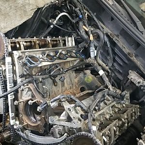
I posted a few pics of the bigger valve cut open valve seat. From the advice ive been given, this is about the maximum this valve seat can be cut, long as the cylinder temperatures are in the normal range. Nothing real hot. Ill most likely be running a gasoline and E85 blend, something like a 50/50 mix like E50, which will bring cylinder temps down below running normal gasoline.

Granted ive spent next to $2500 altogether over the years, just to be able to cut valve seats, but the tooling i have isnt purposed for cutting that much material out. The tooling is really only for bringing seats back and adding angles, but ive figured out how to use them beyond their purpose. It took some practice trial and error, but i got it! Each seat takes roughly 2hrs to cut. Making sure the depths are correct where the valve stem tip is at stock location.
 
OP
OP
96blak54

96blak54

Moderator
Staff
Joined
Feb 21, 2011
Messages
9,977
Reaction score
2,807
Location
In the shop
what ever happened to the rods project you were making?
I still have them. Me being stubborn not wanting to shed $250 to get the big end honed to size, i took upon myself to do the finish size with my tooling,....which in the end was a fail. Now they egg shaped and to big. Im also finding out the material i used may not be idea. Its a 7031 aluminum which is a hard, unforgiving type of aluminum in the environment it would be in. Supposedly the 4000 series aluminum favors better.

I started to correct the rods to be finished hone by someone capable, but i gave up. I decided to move forward with them being as trophies...lol. Ill make a little platform to mount them on so the stand up or lay down. Maybe polish up some pistons to mount on them....heck i dont know. I definitely wont get the $550 i spent on material making them.
 

ttocs

Post Whore
Joined
Oct 9, 2009
Messages
32,383
Reaction score
5,557
Location
Evansville Indiana
I was afraid something like that happened. It was a cool project needless to say, I enjoy seeing your work.
 
OP
OP
96blak54

96blak54

Moderator
Staff
Joined
Feb 21, 2011
Messages
9,977
Reaction score
2,807
Location
In the shop
I appreciate the compliment! Ill agree, it is fun to see another mans creation and i always find what you do to be top notch!
 
OP
OP
96blak54

96blak54

Moderator
Staff
Joined
Feb 21, 2011
Messages
9,977
Reaction score
2,807
Location
In the shop
Here is a finished port comparison to a stock port. Kinda looks the same, but the bigger valve port is much wider and roughly 30minutes of port work material removal, valve seat blending.

20230617_083827.jpg
20230617_083731.jpg
 
OP
OP
96blak54

96blak54

Moderator
Staff
Joined
Feb 21, 2011
Messages
9,977
Reaction score
2,807
Location
In the shop
Here is the bigger valve installed and raised roughly .050" off the seat. Valve completely seated is flush with the chamber. Which created a pocketed wall around the edge of the valve. To get above the newly created pocket wall, the valve lift had to be around .100" before any real clear line of sight path could be seen. Pictures show this wall laid back while the valve around .050" lift.

20230801_105459.jpg20230801_105534.jpg
 
OP
OP
96blak54

96blak54

Moderator
Staff
Joined
Feb 21, 2011
Messages
9,977
Reaction score
2,807
Location
In the shop
Pictured here is the exhaust valve at a lift of around .300" and the chamber wall shrouding. All i did was use some layout fluide, lay the head gasket to be used in place and scribe a line. As you can see a good .100" shrouds the valve. It gets worse at lower lifts. So using a junk valve while using my porting tools, i laid this shrouding back.

20230803_090208.jpg
20230803_090104.jpg
 
OP
OP
96blak54

96blak54

Moderator
Staff
Joined
Feb 21, 2011
Messages
9,977
Reaction score
2,807
Location
In the shop
Thanks

Im hoping all the little tricks will squeeze some respectable power from all these junk components. Its not about what everyone knows what works good. Its all about the challenge for me. Take underdog performers and bring them to life.

Doing this has been alot of work, but also alot of fun. I cant say i haven't enjoyed the work load. It be nice if i had the tooling that can knock out the work quicker, but it is what it is. I have been eyeballing some 3 angle valve seat cutters for the milling machine.

Also ive been looking at performance trends flow bench setup. I think ill make a thread about it. Get some feed back from others about it.
 
OP
OP
96blak54

96blak54

Moderator
Staff
Joined
Feb 21, 2011
Messages
9,977
Reaction score
2,807
Location
In the shop
1000001141.jpg1000001140.jpg

Ill be running an edelbrock manifold which is pi style geometry including the pi intake manifold style gaskets. The npi geometry of the head works with the pi style for most of it except this one water port. The npi water port has a dog leg area that doesnt get sealed up with the pi gasket, so i had it welded up. This area is where a big blob of rtv gets placed when doing a pi manifold swap on npi heads. Instead of placing rtv and the chances of a leak, i had it welded up. Pictured is the weld job and clean up, ported to match the gasket.
 
OP
OP
96blak54

96blak54

Moderator
Staff
Joined
Feb 21, 2011
Messages
9,977
Reaction score
2,807
Location
In the shop
Plan is to use every bit of possible trick i know to squeeze what i can.

Probably 20hp over stock
 

Latest posts

Forum statistics

Threads
77,435
Messages
1,502,107
Members
14,917
Latest member
virocanah

Members online

Top