96blak54 on going projects

OP
OP
96blak54

96blak54

Moderator
Staff
Joined
Feb 21, 2011
Messages
10,076
Reaction score
2,923
Location
Lawrenceburg Kentucky
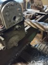
Placing the engine bore machining set up on hold for a few tools i need to modify. Like a 6" long extension facemill adapter for unavailable spindle tooling. Desire is to use the 2" diameter facemill i currently have, but in its self poses problems due to its size. Any tool taking lateral force will have a deflection add 6" extention to that tool, the deflection gets worse and this extension has to be a smaller diameter than the tool so it doesnt interfere with what has been cut, so that makes the extension diameter something around 1.900". Or I could drop $1000 on a new 3" facemill, uping the meat of the extension to 2.900"......i think ill give what i have on hand a try 1st. So stay tuned for more action on this one.
 
Last edited:
OP
OP
96blak54

96blak54

Moderator
Staff
Joined
Feb 21, 2011
Messages
10,076
Reaction score
2,923
Location
Lawrenceburg Kentucky
Back to the camshaft grinder!!!
Its been awhile and during the time ive brainstormed how to get the camshaft rotating and be functional with not to much involved with its process, parts purchased, machine work and such. Here is what i came up with.


Its simple to mount on and off the machine. It doesnt have to be exact, but needs to be rigid. Its a window drive motor from a Crown Victoria. The video shows its purpose, but not shown is the grinder in full funtion. The battery i used to temporarily drive the window motor was almost dead. Plan is to use an ac/dc power supply with some healthy amperage. This setup might be to fast in rotation, i dont know. Im a fan of slow and steady, but this is a start and lets see where it takes us. I still need to add a spring to keep the cam pattern tensioned to the deadwheel and then we will be able to grind lobes handsfree. Keep watching
 

ttocs

Post Whore
Joined
Oct 9, 2009
Messages
32,715
Reaction score
5,700
Location
Evansville Indiana
Ha very cool dude. I watched it before I read the description and wondered if that was a power window motor. how do are you going to control the lobes of the cam to shape them properly?
 

Musturd

Post Whore
Joined
Feb 12, 2011
Messages
10,542
Reaction score
2,330
These are some valuable skills and tools to have . Nice work . I didn’t notice the little shim at first
 
OP
OP
96blak54

96blak54

Moderator
Staff
Joined
Feb 21, 2011
Messages
10,076
Reaction score
2,923
Location
Lawrenceburg Kentucky
Thank you gentlemen! Much obliged!

ttocs, if you notice the hub driven by the window motor and look close, youll see a thin metal within the outside groove of that hub. It is the pattern and that hub and pattern articulate from the stationary wheel mounted in the back causing the shaft to cam against the belt grinder. Look close at the hub youll see is actually 2 pieces to this hub. The pattern hub side slips over an arbor to the other hub with the 8 socket head bolts. The 8bolt hub is bolted solid to the camshaft(the center drive bolt) and offers 8 different position for 8 different degree of cam lobe locations that that pattern side can switch to. I get a little bit of time, ill do a video of it broke down.
 

ttocs

Post Whore
Joined
Oct 9, 2009
Messages
32,715
Reaction score
5,700
Location
Evansville Indiana
I see it now. How do you find the right shape do you calculate and machine the pattern yourself
 
OP
OP
96blak54

96blak54

Moderator
Staff
Joined
Feb 21, 2011
Messages
10,076
Reaction score
2,923
Location
Lawrenceburg Kentucky
An idea, useful tools like cad program and cnc machine, trial and error....its the wisedom gained.

For instance, most cams have performance potential such as a modular pi cam. All the valve events are there to be a low performing off the shelf aftermarket type cam in stock form and a few more hp can be extracted massaging some of the valve events. Taking a small amount of material from the base circle, adding the adjacent amount of shim under the lash adjuster to keep geometry correct, i can integrate a longer duration valve events and not cost much.

No mater what engine, how its built, how it runs, an improvement to the cam can always extract a little more performance. Even if someone specs a cam for your engine build with all the latest greatest computer modeling, 3 more improved versions of that same cam can be had and will perform better. If you want to keep said cam improvements a secret, you must be able to do the work yourself. Most times a simple change in lobe seperation angle will net you more power n/a. Keep in mind lsa is the middle point of both lobes open and close event center line and at what angle the centerlines are relative to each other. Knock off 10degree off EO will affectively change the lsa. Itll be tighter. Lobe max lift has nothing to do with lsa.
 
Last edited:

ttocs

Post Whore
Joined
Oct 9, 2009
Messages
32,715
Reaction score
5,700
Location
Evansville Indiana
thanks again. The idea of making what you did amazes me but then when I considered how much goes into the overlap/duration/height/ect it really is impressive.
 
OP
OP
96blak54

96blak54

Moderator
Staff
Joined
Feb 21, 2011
Messages
10,076
Reaction score
2,923
Location
Lawrenceburg Kentucky
Thank you
You know at one point in time, cam information and understanding was very gray to me. It took me setting up a station of a couple of dial gauges and degree wheel to get my hands wet in and to understand what is goes on. It would take you less time than i did understanding it. You are pretty sharp!
 

RAU03MACH

Legend
Joined
Apr 23, 2019
Messages
6,904
Reaction score
6,747
Location
NEW MEXICO
How much harder could it be doing a push rod cam
If you figure that one out let me know
I'll probably send out some over head cams one day
When I get time and cash
 

d.garza18

Active Member
Joined
Jun 23, 2017
Messages
687
Reaction score
146
Location
TEXAS
Still have yet to put the 5.4 cams you did for me to use, soon though!
 
OP
OP
96blak54

96blak54

Moderator
Staff
Joined
Feb 21, 2011
Messages
10,076
Reaction score
2,923
Location
Lawrenceburg Kentucky
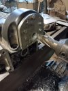
So on this episode of 96blak54 projects we are performing an alternate solution to electronic fuel injection and ingnition timing by first figuring out a way to mount a distributor and be driven by the camshaft. After much collaboration with an ingenious, hands down super brain(lwarrior) this is what we came up with.
1000001759.jpg
1000001760.jpg

Now ideally, a fiberglass/composite type valve cover isnt really thought as stable enough for what im trying to achieve. An all aluminum valve cover makes better sense, but if you think about it, all the distributor is doing is spinning and no real tortion is being applied to where the structural of the valve cover is compromised.

If you notice in the 1st pic, i was performing the machine work with out any support to the front edge of the valve cover. Although the valve cover was adequate rigid enough while machining, i decided to hack up a front cover and then bolt it all up in a running scenario and then machine with a bigger tool. I will say it is very very very rigid. To be able to withstand the pressures of machining especially with dull high speed tooling is really good. My expectations with this project was failure and iexpected the valve cover to give out, break, otherwise fail, but to my surprise the rigidity of this was amazing.

You maybe asking. Why not just purchase aluminum valve covers and make things less complicated? Well i did. The aluminum valve covers are larger and not as conformed to the head like the composite covers are. If i were running a 4.6l this wouldnt be a problem, but since my duma$$ swapped in a giant wide 5.4l, their would be clearance for the brake reservoir or shock towers. It gets pretty tight in there!

As of right now, in its development stage, it looks like trash. Not much time was spent on presentable asthetics. What you see is a plate of aluminum on the front carved out in the shape of the cover bolted to an internal steel plate carved out to fit correctly, drilled and tapped and together sandwiching the valve cover material. Then mounted the head on the mill, camshaft installed, indicate the camshaft center line, then mount the valve cover and machine a hole for a distibutor to mount into and be driven by the camshaft. In the final results, those bolts wont be used, the bolt pattern has since been changed, and a thicker internal plate will be used along with socket style flat head bolts thatll be flush with the front plate.

A distributor still needs to be purchased and hacked up to fit. Ive found some cheap ones for $70 off ebay that looks like great candidates. Also a way to dial the dist and lock it down in place needs to be figured out. Its all a work in progress.
 

Musturd

Post Whore
Joined
Feb 12, 2011
Messages
10,542
Reaction score
2,330
Nice the first time I seen this done was on a friends 5.4 4v turbo fox . I seen the distributor in the front and was like wtf
 
OP
OP
96blak54

96blak54

Moderator
Staff
Joined
Feb 21, 2011
Messages
10,076
Reaction score
2,923
Location
Lawrenceburg Kentucky
Yes. Same with me. But back then researching valve cover distributor or similar like scenario, i found that car manufacturers used the idea with alot of engine models. Mostly 4 cylinders.
 

Latest posts

Forum statistics

Threads
77,552
Messages
1,504,805
Members
15,019
Latest member
Srchop16

Members online

Top