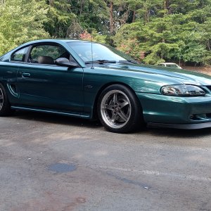
I enjoy reading the builds that happen so here is mine on this 95 GT that I picked up where the complete top end was off for 3 yearsish. Guy lost interest and had to move when I swept in and bought it, a little bit of a crap shoot but thought there were enough new parts to get my cash back if it was a bust. It came with GT40P heads and intake, MAC headers, new 70mm throttle body, cold air intake, new cam with roller lifters, all the gaskets to but back together. All the original stuff came with it as well and new tires on the original wheels too.
View attachment 30948View attachment 30955View attachment 30949View attachment 30950View attachment 30951View attachment 30952
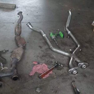
So once i cleaned out the pistons with the vac, air and then wiped oil in each cylinder until they came up clean, I threw the rebuilt heads on(new TF springs) and just set the rest to see what it would look like. Headers had to be clearanced on cylinder #3 runner for the reg. plug to fit. Needing to get ARP header bolts to finish install.
View attachment 30954

.jpeg")