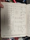
Pedro's helper here. From what Pedro is saying, everything seems accurate. We confirmed that the leakage to ground on the LTGRN/Yel line at the fuel pump harness connector only appears when the PCM is connected, and all other circuits/connectors are isolated. I tend to believe that this small leak is a path to ground via PCM circuitry. What is unknown is the driving force behind the FPR relay coil. The relay is energized from startup (normal) opening the circuit path from the CCRM to pins 30 & 87a then ultimately to the pump. From what I've read, at >3250rpm, the PCM should cut the driving signal to the FPR, de-energizing that relay, and closing the circuit path from CCRM full body voltage to the pump. The FPR and Resistor are wired in parallel so as to create a low output/high output scenario from the pump. Looking at the CCRM I/O, I'm inclined to ask if the Tach signal into the PCM, or maybe it was the CCRM, is the driving force for the change. This tach signal is shown on page 1 of 2 from the book we are working through. If the tach signal isn't being processed correctly, or the CCRM is failing, I'm curious if this is what is keeping the FPR latched up.
I also agree with ttocs that having installed the jumper across FPR 30 & 87a, to supply full voltage to the pump, and not seeing that much of a difference, would point me in the direction of a fuel delivery issue. So in my mind, we have two issues on the table.