Here is my latest escapade.
For the last 5ish years. Ive been tinkering around building a camshaft grinder, mostly centered around grinding modular ford cams, but does accept any cam with nearly 30" length.
My first go at grinding i had it set up similar like an actual cam grinder. Using a grinding wheel to remove tge material only to find the difficulties of dressing the wheel after every lobe grind. Grinding wheels load up with material and need to be brought to square after each grounded lobe. Doing so posed time consuming process and not cost effective at all. Also the grinding wheel process wasnt smooth and required strong stabilization so that the wheel or cam doesnt bounce away when being ground. The bounce showed up into the grounded lobe, producing a ripple on the lobe. A softer grind wheel could be used to correct the ripple but again costs and keeping it dressed.
All mathematics and machine work to get the grinding wheel motor all situated, after much debate with myself, i scraped the idea in favor of a small mini belt grinder/sander.
Off to harbor freight to view a possible selection upgrade and luck would have it, they had one. $100 later and a few extra belts of different grades, i found myself disassembling parts not needed. Like the side mounted disc grinder and bottom mounting plate or the steady rest for the grinders.
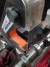
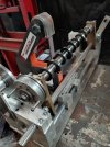
A new mounting plate had to be made to adapt the belt grinder to the machines cross slide and i had to raise all of the camshaft mechanisms 4" with some aluminum blocks, so that the camshaft lobe meets the grinders belt backing plate. Turns out that backing plate was flimsy and after a few lobe grinds it had to go in favor of something solid. A few ours on the mill with some angle iron made all the difference. Now it grinds smooth and effortless and after each lobe, when the belt is worn, i simply replace the belt...$2.50. Ive since discovered i can grind 2 lobes per belt.
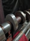
Each lobe with the pattern i have set takes roughly 25min to grind. 120grit belts prove to produce a real nice finish while helping to keep time spent to a minimum. Best of all, these belts are local and always in stock.
For the last 5ish years. Ive been tinkering around building a camshaft grinder, mostly centered around grinding modular ford cams, but does accept any cam with nearly 30" length.
My first go at grinding i had it set up similar like an actual cam grinder. Using a grinding wheel to remove tge material only to find the difficulties of dressing the wheel after every lobe grind. Grinding wheels load up with material and need to be brought to square after each grounded lobe. Doing so posed time consuming process and not cost effective at all. Also the grinding wheel process wasnt smooth and required strong stabilization so that the wheel or cam doesnt bounce away when being ground. The bounce showed up into the grounded lobe, producing a ripple on the lobe. A softer grind wheel could be used to correct the ripple but again costs and keeping it dressed.
All mathematics and machine work to get the grinding wheel motor all situated, after much debate with myself, i scraped the idea in favor of a small mini belt grinder/sander.
Off to harbor freight to view a possible selection upgrade and luck would have it, they had one. $100 later and a few extra belts of different grades, i found myself disassembling parts not needed. Like the side mounted disc grinder and bottom mounting plate or the steady rest for the grinders.
A new mounting plate had to be made to adapt the belt grinder to the machines cross slide and i had to raise all of the camshaft mechanisms 4" with some aluminum blocks, so that the camshaft lobe meets the grinders belt backing plate. Turns out that backing plate was flimsy and after a few lobe grinds it had to go in favor of something solid. A few ours on the mill with some angle iron made all the difference. Now it grinds smooth and effortless and after each lobe, when the belt is worn, i simply replace the belt...$2.50. Ive since discovered i can grind 2 lobes per belt.
Each lobe with the pattern i have set takes roughly 25min to grind. 120grit belts prove to produce a real nice finish while helping to keep time spent to a minimum. Best of all, these belts are local and always in stock.