Oil temp gauge still not working

Daryl

Well-Known Member
SN95 Supporter
Joined
Apr 5, 2020
Messages
2,915
Reaction score
1,389
Location
SoCal
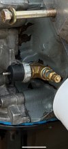
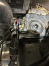
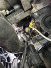
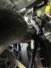
I recently installed the gauge bezel I picked up from Maximum95’s “Parting out” sale. It has the air:fuel gauge on the left and Oil Temp on the right. Both came with all wires still attached. The air:fuel is working (#’s displaying, bouncing all over the place!) but the oil temp still is not. They both worked in Max’s, but for the life of me I can’t figure out why it’s not working in mine.

Any suggestions on how to trace? You guys know how ridiculously terrible I am with electrical, so any help at the “Electrical Shit for Dummies “ level would be greatly appreciated!

Harumph!! :-(
 

Attachments

  • IMG_0613.jpeg
    IMG_0613.jpeg
    94.3 KB · Views: 14
  • IMG_1585.jpeg
    IMG_1585.jpeg
    169.9 KB · Views: 14

ttocs

Post Whore
Joined
Oct 9, 2009
Messages
32,663
Reaction score
5,669
Location
Evansville Indiana
how do you have the sender ground, grounded? There should be two wires going to the sender and sometimes people think that the sender ground is the same as the chassis ground and will put the two together. The + signal for the sender goes to the top of the sender, ideally the sender ground has a ring terminal that goes on the other side of the sender nice and tight. That is basically a chassis ground but if you just put it on the chassis then there is the resistance of the teflon tape/sealer to the sender that can cause problems and it depends on the resistance reading to know what is going on.
 
OP
OP
Daryl

Daryl

Well-Known Member
SN95 Supporter
Joined
Apr 5, 2020
Messages
2,915
Reaction score
1,389
Location
SoCal
how do you have the sender ground, grounded? There should be two wires going to the sender and sometimes people think that the sender ground is the same as the chassis ground and will put the two together. The + signal for the sender goes to the top of the sender, ideally the sender ground has a ring terminal that goes on the other side of the sender nice and tight. That is basically a chassis ground but if you just put it on the chassis then there is the resistance of the teflon tape/sealer to the sender that can cause problems and it depends on the resistance reading to know what is going on.
I see you don’t sleep much either! Wasn’t expecting a reply at this hour, but I will retrace after the sun comes up, take pics/post and see what we see.
 

ttocs

Post Whore
Joined
Oct 9, 2009
Messages
32,663
Reaction score
5,669
Location
Evansville Indiana
I am not much of a morning person but my stomach problems like to wake me up around 430 or so.
 

ttocs

Post Whore
Joined
Oct 9, 2009
Messages
32,663
Reaction score
5,669
Location
Evansville Indiana
is there a negative/ground/- wire that is supposed to go along with that white wire kind of like a speaker wire has a +/- in addition to the power ground? If you can show the circuit diagram that they recommend having
 
OP
OP
Daryl

Daryl

Well-Known Member
SN95 Supporter
Joined
Apr 5, 2020
Messages
2,915
Reaction score
1,389
Location
SoCal
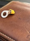
I’m redoing this. Should it have been crimped to the wire itself, not the wire sleeving?
image.jpg
Could that prevent conductivity?
 
OP
OP
Daryl

Daryl

Well-Known Member
SN95 Supporter
Joined
Apr 5, 2020
Messages
2,915
Reaction score
1,389
Location
SoCal
I removed the extra length of wire that I spiced in and reattached as such;

image.jpgimage.jpg

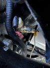
Still don’t know WTF that red thing is. Any ideas? Is it correct? Necessary? IDK
 

ttocs

Post Whore
Joined
Oct 9, 2009
Messages
32,663
Reaction score
5,669
Location
Evansville Indiana
not sure what kind of connector that is. Is it your stock gauge or the aftermarket that is not working?
 
OP
OP
Daryl

Daryl

Well-Known Member
SN95 Supporter
Joined
Apr 5, 2020
Messages
2,915
Reaction score
1,389
Location
SoCal
That's totally the reason why.

The red thingy is what you might call a ghetto wire splice.
Ok, I’ve got it crimped onto the actual copper wires themselves. Fingers crossed next time I drive it I’ll get an oil temp reading!
 

95opal

Well-Known Member
Joined
Jun 21, 2007
Messages
3,028
Reaction score
1,613
Is that big ground wire stud in the timing cover?
 
OP
OP
Daryl

Daryl

Well-Known Member
SN95 Supporter
Joined
Apr 5, 2020
Messages
2,915
Reaction score
1,389
Location
SoCal
Is that big ground wire stud in the timing cover?
You mean that huge-ass brass looking monster of a bolt that’s screwed in there for no apparent reason??
Beats the f*ck out of me!
 
OP
OP
Daryl

Daryl

Well-Known Member
SN95 Supporter
Joined
Apr 5, 2020
Messages
2,915
Reaction score
1,389
Location
SoCal
That huge-ass bolt screwed in there for no apparent reason is screwed into the cylinder head, if memory serves, but I’ll have to double check to be sure
 

ttocs

Post Whore
Joined
Oct 9, 2009
Messages
32,663
Reaction score
5,669
Location
Evansville Indiana
looks like the red connector is to the factory sender, not the aftermarket. It should have no effect on the other gauge or sender that does not seem to have a ground. I need to get a pic of mine to show you but the senders I have that look like that there is the signal wire on the top(where you have the white wire) and then on the other side of that short little sender is the ground side. On mine I have a ring terminal that is on the bottom side where it screws into the oil connection with a washer or two to ensure it has a tight fit. If you just use the chassis ground what happens is it looks like the signal would either have to go through 3 connections that are are teflon wrapped, or use the oil itself to transfer the signal ground. Either of these options is going to add resistance to the circuit which is how it tells how much pressure it is reading. Changing the resistance will change the reading on the gauge.
 
OP
OP
Daryl

Daryl

Well-Known Member
SN95 Supporter
Joined
Apr 5, 2020
Messages
2,915
Reaction score
1,389
Location
SoCal
thank you, Scott. A picture like that could show me a lot and help solve this issue.
 

ttocs

Post Whore
Joined
Oct 9, 2009
Messages
32,663
Reaction score
5,669
Location
Evansville Indiana
I just went out to look to see if I could get a pic but I have done such a good job at tucking/hiding my wiring that at 4 am in a dark garage the only sender/sensor I can really see and get a pic of is the fuel pressure sensor. I will try when the sun comes up to see if it helps but all you can really barely see is the gold ring terminal on the bottom of the sensor, the wires are all tucked back behind it.

I am willing to bet that is the problem though because as I look at all the adaptors you had to put on to get the temp sensor it looks like there are 4 threaded/insulated connections between the ground portion of the sender and the block. If you had it mounted more directly mounted to the block it would probably work with a chassis ground but without the ground on the sender like I am talking the resistance reading is off.

Do you know what brand the gauge is?
 

weendoggy

Active Member
Joined
May 31, 2019
Messages
640
Reaction score
733
From me just going through this, it looks like someone put a makeshift "T" on the oil pressure to read to two gauges (or another item). One will go to the stock dash gauge and is usually a white/red stripe wire. Stock does not require a separate ground wire. It grounds through the switch to ground when o/p is seen.

The other sender on the brass "T" fittings is to a separate gauge (aftermarket). The large stud is a ground in the side of the timing cover for ground. Not sure what gauge package doo-dah you bought, but if it only has two terminals, one will be ground and the other to the sender.

The stock setup doesn't use a separate ground due to it being done within the chassis/engine harness.
 

Latest posts

Forum statistics

Threads
77,520
Messages
1,504,176
Members
14,985
Latest member
Suprasuavy

Members online

Top