FivepointSlow
Well-Known Member
This write up has been done a few times but you may have run into the problem I did when I was researching this project, that all the old write-ups for 96-98 vertical exports lead to dead links. An unfortunate reality to abandoned forums. I wanted to share what I found and how I achieved this mod so others don't have to dig through the internet and reach out to others in hopes someone can walk them through it.
This write up can be used for all 96-04 Mustangs with vertical taillights and 94-95 horizontal taillights if you can ignore the presence of an extra light bulb.
94-95 guys can also go here for a detailed write up on their horizontal taillights.
http://www.chythar.net/mustang/mustang_94-95_export_taillight_installation.html
PART 1.1
Firstly we need to tackle the wiring harness on the taillights themselves.
It should be noted I am not using the export harness. I am using what I would imagine we can refer to as the US or North American harness. If you are using the export harness skip to PART 1.2
The problem with this harness is 2 fold. For one the harness is not equipped with the socket for the amber turn signal, this is because your stock taillight assemblies came with that socket blocked off as that part of the taillight is used as a reflector with no bulb.
US taillight assembly

Export taillight assembly

To modify this harness you will need either a second set of harness' or the appropriate pigtails. I picked up another set of harness' off of someone who upgraded to the Raxiom Sequential harness on their car. You can also find these harness in your local U-Pick salvage yard or from a part out vehicle.

This is what we need to achieve, This is identical to your stock harness but with the addition of a grey 2 tab socket from the donor harness. The amount of tabs are important. Luckily the export turn signal socket uses the same socket as the reverse bulbs, so the reverse sockets from the donor harness' will be used as our new turn signal sockets.
To add the reverse socket onto your harness as a turn signal bulb we have to tap the black wire into another ground in the harness, it doesn't matter where this is done in the harness as all of the black wires in the harness merge into a single ground wire by the time it reaches the pigtail on the body side of the harness. The other wire on the new socket needs to be lengthened so it can follow the harness, go through the rubber grommet, and end right before the end of the body side pigtail. I ended mine about 1.5 inches from the end of the harness.
Now that the new socket is grounded and the power wire for it is ran along the length of the harness, we need to cut the brake/turn signal wire of our harness. The color of this wire may vary from year to year, on my car it was green/purple on one side and orange/green on the other.
You can easily tell regardless of color because the grounds will always be black and the parking light should always be brown, but to double check the parking wires will go into the middle of your sockets (Labeled Minor) and the brake wires will go to the outside of the socket (Labeled Major) shown here

Once you've identified which color wire you need to cut, you will see at the end of the harness there are 2 of the same wire that go into 1 pin in the connector. We want to cut both wires, and attach the 2 wires coming from the connector to the new wire we just ran to the new socket. This will be your turn signal wire.
Now you can tape up the harness and make it look nice and neat again but don't forget to leave the 2 cut wires sticking out of the harness, I used a bullet connector for these as we are going to run them farther and tap into the third brake light wiring for a brake light signal. I wanted to keep the taillight assemblies easily removable if need be down the road so I chose to use the bullet connector as oppose to a butt connector or soldering, but this is up to you.

OPTIONAL: What I ended up doing while I had the extra pigtails from the donor harness, was replaced the grey 3 tab socket with a black 3 tab socket from the donor harness so I could run a 3157 bulb instead of a 3156 bulb, this allows the inner most red bulb to still act as a parking light but now in addition we can use the brighter filament as an additional brake light

Match the ground and parking light wires to the previous wires for that socket location, and simply tap the pigtail next to it for the brake signal.

PART 1.2
If you are using your stock US harness, you can skip to PART 2
If you are using the Export harness, the wiring is much simpler. All we have to do is cut the body connector off your old stock harness, and match the wires accordingly, connecting ground (black), parking (brown), reverse(can vary), and turn signal(can vary) to each other. To verify what color your turn signal is check the wires coming out of that socket on the taillights, and connect that to the 2 wires that share the same pin in the body connector, and do the same with the reverse but connect that to the single wire left in the harness.
Wrap up the harness and leave the 2 brake light wires sticking out so you can run them farther in the next part.
PART 2
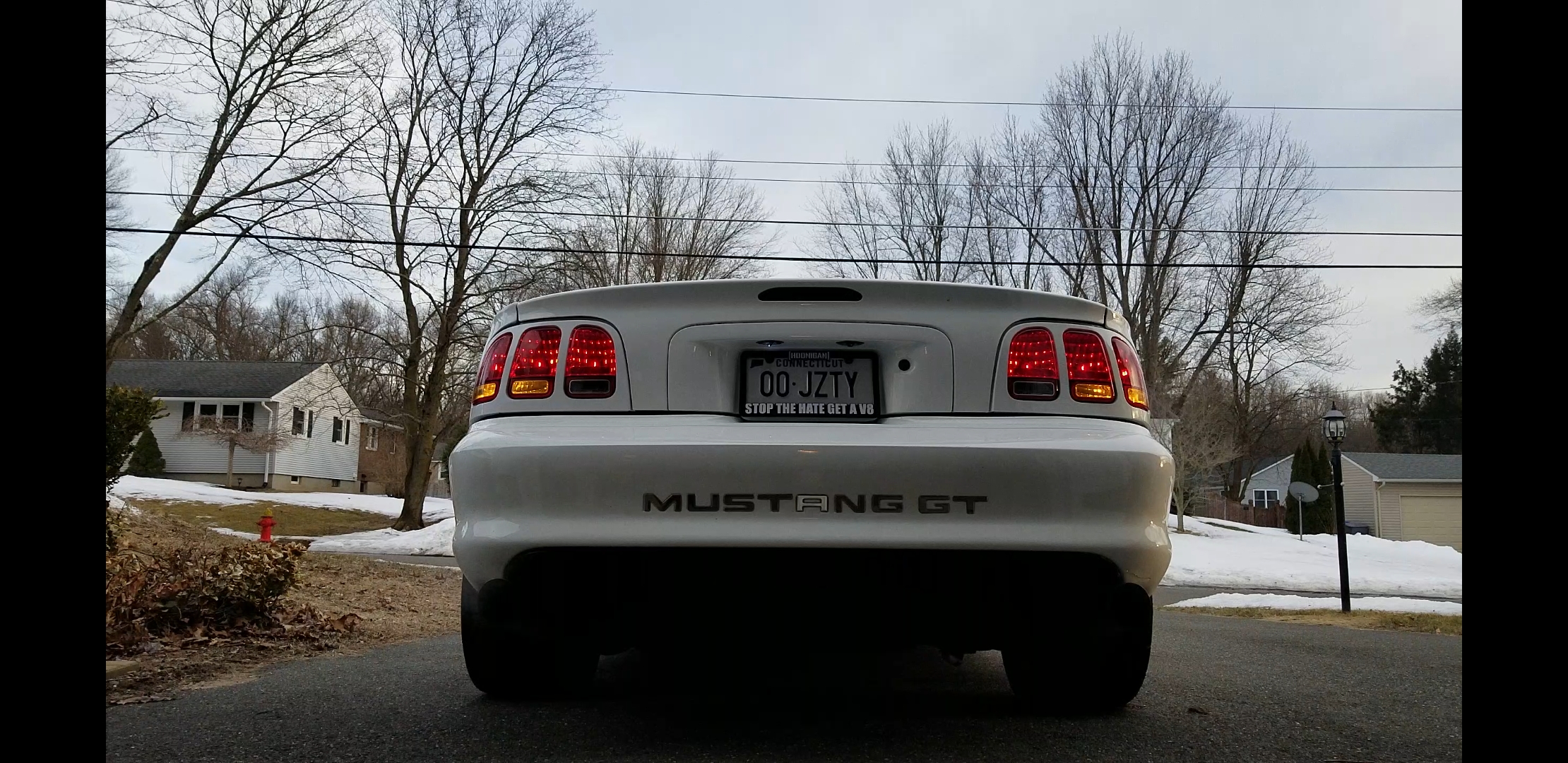
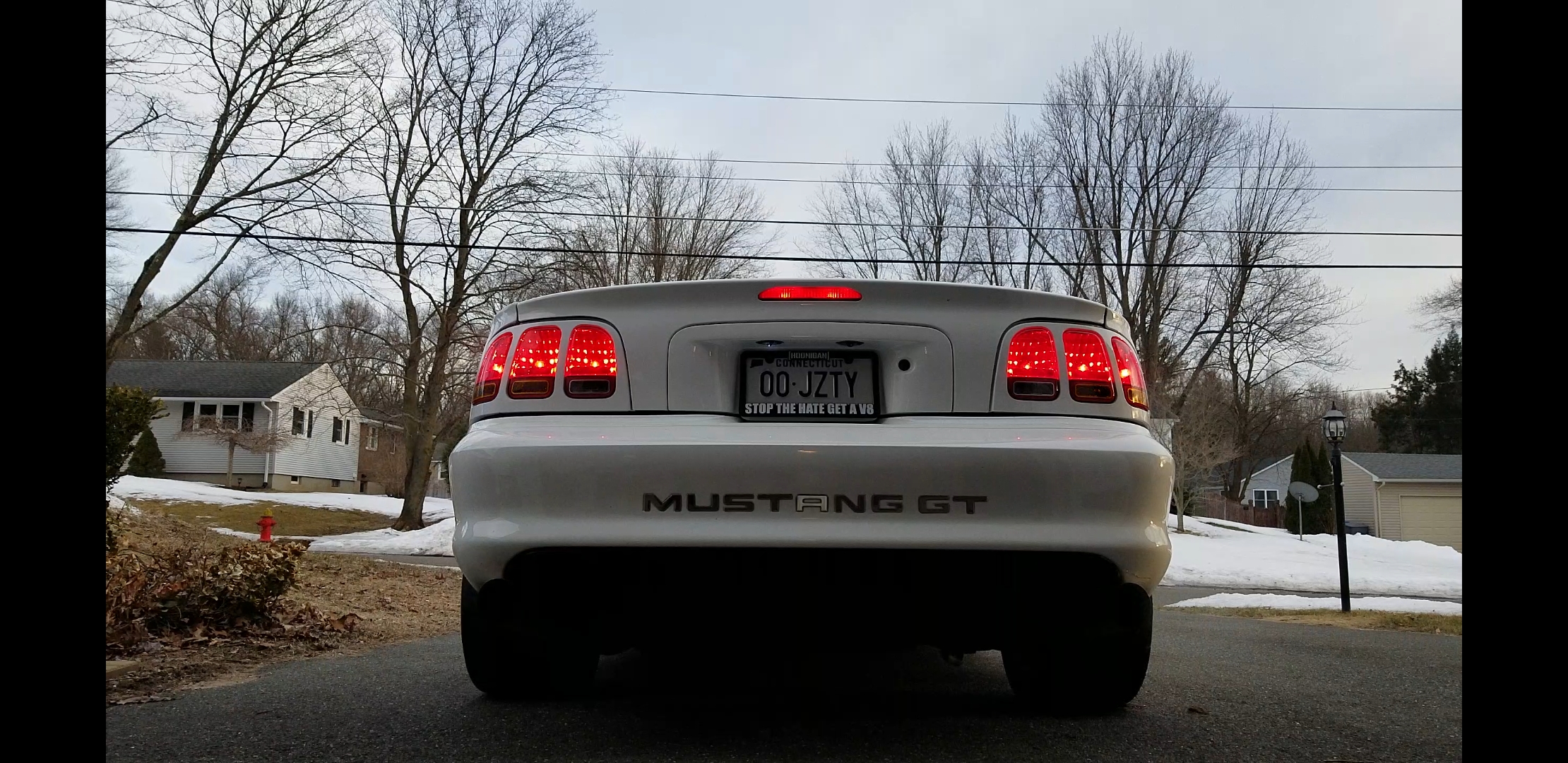
Now the wiring for the taillight assemblies is done, and we can reinstall the taillights onto the vehicle.
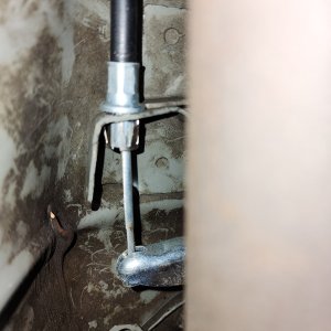
We now need to get a brake signal to the taillights. The easiest way I found to do this was to inspect the third brake light, identify the 2 bulbs used for the brake light, and the color of the wire that is not ground(black). Follow this wire to the grey connector and now identify the color of the wire on the other side of that connector. Mine was red/green.
Now we know what color wire we will need to tap into. Follow the trunk harness to behind the trunk side panel and find that connector, unplug the connector so it is easier to work with, and tap into the wire you need (in my case red/green). I added another bullet connector to allow for the easy removal of that plug in the future. Now run a wire to the left taillight assembly, and then from there to the right assembly. I used 14ga wiring as that is what I had, stock I believe all of the taillight wiring is 18 or 16ga, just don't use anything smaller than stock to prevent any potential hot wiring.
Now the trunk side of the wiring is done. But we are not done yet!
Currently we have a problem. Your turn signals work as intended, however when the brakes are applied the turn signals will illuminate aswell.

This is because we are using the old brake/turn signal wire for our turn signals, and we need to convert this wire into a turn signal only wire.
This write up can be used for all 96-04 Mustangs with vertical taillights and 94-95 horizontal taillights if you can ignore the presence of an extra light bulb.
94-95 guys can also go here for a detailed write up on their horizontal taillights.
http://www.chythar.net/mustang/mustang_94-95_export_taillight_installation.html
PART 1.1
Firstly we need to tackle the wiring harness on the taillights themselves.
It should be noted I am not using the export harness. I am using what I would imagine we can refer to as the US or North American harness. If you are using the export harness skip to PART 1.2
The problem with this harness is 2 fold. For one the harness is not equipped with the socket for the amber turn signal, this is because your stock taillight assemblies came with that socket blocked off as that part of the taillight is used as a reflector with no bulb.
US taillight assembly
Export taillight assembly
To modify this harness you will need either a second set of harness' or the appropriate pigtails. I picked up another set of harness' off of someone who upgraded to the Raxiom Sequential harness on their car. You can also find these harness in your local U-Pick salvage yard or from a part out vehicle.
This is what we need to achieve, This is identical to your stock harness but with the addition of a grey 2 tab socket from the donor harness. The amount of tabs are important. Luckily the export turn signal socket uses the same socket as the reverse bulbs, so the reverse sockets from the donor harness' will be used as our new turn signal sockets.
To add the reverse socket onto your harness as a turn signal bulb we have to tap the black wire into another ground in the harness, it doesn't matter where this is done in the harness as all of the black wires in the harness merge into a single ground wire by the time it reaches the pigtail on the body side of the harness. The other wire on the new socket needs to be lengthened so it can follow the harness, go through the rubber grommet, and end right before the end of the body side pigtail. I ended mine about 1.5 inches from the end of the harness.
Now that the new socket is grounded and the power wire for it is ran along the length of the harness, we need to cut the brake/turn signal wire of our harness. The color of this wire may vary from year to year, on my car it was green/purple on one side and orange/green on the other.
You can easily tell regardless of color because the grounds will always be black and the parking light should always be brown, but to double check the parking wires will go into the middle of your sockets (Labeled Minor) and the brake wires will go to the outside of the socket (Labeled Major) shown here
Once you've identified which color wire you need to cut, you will see at the end of the harness there are 2 of the same wire that go into 1 pin in the connector. We want to cut both wires, and attach the 2 wires coming from the connector to the new wire we just ran to the new socket. This will be your turn signal wire.
Now you can tape up the harness and make it look nice and neat again but don't forget to leave the 2 cut wires sticking out of the harness, I used a bullet connector for these as we are going to run them farther and tap into the third brake light wiring for a brake light signal. I wanted to keep the taillight assemblies easily removable if need be down the road so I chose to use the bullet connector as oppose to a butt connector or soldering, but this is up to you.
OPTIONAL: What I ended up doing while I had the extra pigtails from the donor harness, was replaced the grey 3 tab socket with a black 3 tab socket from the donor harness so I could run a 3157 bulb instead of a 3156 bulb, this allows the inner most red bulb to still act as a parking light but now in addition we can use the brighter filament as an additional brake light
Match the ground and parking light wires to the previous wires for that socket location, and simply tap the pigtail next to it for the brake signal.
PART 1.2
If you are using your stock US harness, you can skip to PART 2
If you are using the Export harness, the wiring is much simpler. All we have to do is cut the body connector off your old stock harness, and match the wires accordingly, connecting ground (black), parking (brown), reverse(can vary), and turn signal(can vary) to each other. To verify what color your turn signal is check the wires coming out of that socket on the taillights, and connect that to the 2 wires that share the same pin in the body connector, and do the same with the reverse but connect that to the single wire left in the harness.
Wrap up the harness and leave the 2 brake light wires sticking out so you can run them farther in the next part.
PART 2
Now the wiring for the taillight assemblies is done, and we can reinstall the taillights onto the vehicle.
We now need to get a brake signal to the taillights. The easiest way I found to do this was to inspect the third brake light, identify the 2 bulbs used for the brake light, and the color of the wire that is not ground(black). Follow this wire to the grey connector and now identify the color of the wire on the other side of that connector. Mine was red/green.
Now we know what color wire we will need to tap into. Follow the trunk harness to behind the trunk side panel and find that connector, unplug the connector so it is easier to work with, and tap into the wire you need (in my case red/green). I added another bullet connector to allow for the easy removal of that plug in the future. Now run a wire to the left taillight assembly, and then from there to the right assembly. I used 14ga wiring as that is what I had, stock I believe all of the taillight wiring is 18 or 16ga, just don't use anything smaller than stock to prevent any potential hot wiring.
Now the trunk side of the wiring is done. But we are not done yet!
Currently we have a problem. Your turn signals work as intended, however when the brakes are applied the turn signals will illuminate aswell.
This is because we are using the old brake/turn signal wire for our turn signals, and we need to convert this wire into a turn signal only wire.