AEM Wideband and input into SCT X4 help needed

jfisher

New Member
Joined
Jul 30, 2008
Messages
71
Reaction score
72
Location
Ohio
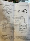
Anyone in here running an AEM wideband with the SCT analog input cable successfully? I am having some issues getting mine to work. Here is how I have it wired:

AEM side
-Red to number 8 fuse via an add a fuse
-Black and brown to ground (crimped together with the 2 grounds from the SCT harness using a ring terminal bolted to the stock fuse box ground bolt)
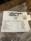
-white analog positive wire going to the orange analog 1 wire on the SCT harness

SCT input harness side
-black and blue crimped together with the black on the AEM side mounted to the stock ground bolt on the interior fuse panel
-orange wire to white wire on AEM side

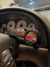
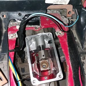
Wideband O2 harness simply ran up through trans tunnel and plugged into back of gauge
The gauge seems to be getting power (see video in comments for exactly what it’s doing), but doesn’t light up at all and doesn’t give any reading even with car running.

I have to be missing something. Any ideas?
 

Attachments

  • AEM Instructions 1.jpg
    AEM Instructions 1.jpg
    224.2 KB · Views: 13
  • SCT Analog Input Cable Instructions.jpg
    SCT Analog Input Cable Instructions.jpg
    156.2 KB · Views: 13
Last edited:
OP
OP
J

jfisher

New Member
Joined
Jul 30, 2008
Messages
71
Reaction score
72
Location
Ohio
Update: I think it's actually the gauge itself and not my wiring :) Wired the gauge directly to the battery for power and ground and it does exactly the same thing. AEM has been great and answered the phone on the first try. Sending them a few purchase confirmation details and their sending me out a new gauge.
 

apsmith49921

Well-Known Member
Joined
Aug 5, 2020
Messages
1,042
Reaction score
890
Fire cable. I have an x3 I was just having trouble getting the parameters set on my data log
 

ttocs

Post Whore
Joined
Oct 9, 2009
Messages
32,654
Reaction score
5,665
Location
Evansville Indiana
if I am reading it correctly it that is a serial info transmitter for if you hook up a serial port to it.
 
OP
OP
J

jfisher

New Member
Joined
Jul 30, 2008
Messages
71
Reaction score
72
Location
Ohio
why do you have the blue wire grounded?
I think I see what you're getting at. Are you thinking the blue Analog 1 ground on the SCT side should go to the brown analog 1 ground on the AEM harness?
 
OP
OP
J

jfisher

New Member
Joined
Jul 30, 2008
Messages
71
Reaction score
72
Location
Ohio
It ended up being the gauge. Everything is working great now. Tapped into fuse 11 for the radio.
 

ttocs

Post Whore
Joined
Oct 9, 2009
Messages
32,654
Reaction score
5,665
Location
Evansville Indiana
I could be wrong but the blue wire/analog ground I would think does not mean that it is supposed to be grounded but is the ground for the analog signal cable if you connect to a pc. Every positive needs to have at least one negative to be a complete circuit and if I am reading it right that blue wire is the ground for the analog signal cable that should just go between the gauge and basically connect to the pc ground.
 
OP
OP
J

jfisher

New Member
Joined
Jul 30, 2008
Messages
71
Reaction score
72
Location
Ohio
I could be wrong but the blue wire/analog ground I would think does not mean that it is supposed to be grounded but is the ground for the analog signal cable if you connect to a pc. Every positive needs to have at least one negative to be a complete circuit and if I am reading it right that blue wire is the ground for the analog signal cable that should just go between the gauge and basically connect to the pc ground.

I have that wire and the brown wire on the AEM side lightly twisted together right now so we'll see what happens. I have a remote tuning session on Monday, April 24th, so will know for sure then if the data is flowing to the SCT X4. Otherwise it's working great and confirming how rich I thought the car might be :)
 

Attachments

  • AEM Wideband.jpg
    AEM Wideband.jpg
    169.2 KB · Views: 2

ttocs

Post Whore
Joined
Oct 9, 2009
Messages
32,654
Reaction score
5,665
Location
Evansville Indiana
I am 99% sure that the brown wire does not go to the battery/car chassis ground or the schematic is drawn all wrong. If they wanted it grounded to the chassis, they would have shown it connecting to the negative terminal on the battery on the bottom with the line/dot like they did the ground. Try disconnecting it or ask your tuner to be sure but either that schematic is drawn wrong or you have it connected wrong. Understand I am not callin ya dum or trying to flex in any way I am just trying to help. I completely understand why you did this but I don't think it is right.
 
OP
OP
J

jfisher

New Member
Joined
Jul 30, 2008
Messages
71
Reaction score
72
Location
Ohio
I am 99% sure that the brown wire does not go to the battery/car chassis ground or the schematic is drawn all wrong. If they wanted it grounded to the chassis, they would have shown it connecting to the negative terminal on the battery on the bottom with the line/dot like they did the ground. Try disconnecting it or ask your tuner to be sure but either that schematic is drawn wrong or you have it connected wrong. Understand I am not callin ya dum or trying to flex in any way I am just trying to help. I completely understand why you did this but I don't think it is right.
Not at all taking offense and appreciate the feedback. I'm not entirely clear on how you're saying to wire it. I did change it after the initial post and I now have it like this:

AEM Side:
-Red power to number 11 radio fuse on interior fuse box
-Black is grounded to interior fuse box ground screw (crimped together with black on SCT side)
-White wire to the orange wire on the SCT side
-Brown to the blue on the SCT side

SCT Side:
-Black is grounded to interior fuse panel ground screw
-Orange wire to the white wire on the AEM side
-Blue wire to the brown wire on the AEM side

Gauge currently works fine as a standalone gauge. Have a remote tuning session this coming Monday. Will know then if the SCT fire cable is operational.
 

garrittpwl

Active Member
Joined
May 15, 2016
Messages
273
Reaction score
261
Location
Indiana
Not at all taking offense and appreciate the feedback. I'm not entirely clear on how you're saying to wire it. I did change it after the initial post and I now have it like this:

AEM Side:
-Red power to number 11 radio fuse on interior fuse box
-Black is grounded to interior fuse box ground screw (crimped together with black on SCT side)
-White wire to the orange wire on the SCT side
-Brown to the blue on the SCT side

SCT Side:
-Black is grounded to interior fuse panel ground screw
-Orange wire to the white wire on the AEM side
-Blue wire to the brown wire on the AEM side

Gauge currently works fine as a standalone gauge. Have a remote tuning session this coming Monday. Will know then if the SCT fire cable is operational.
I'm betting it wasn't operational? I too am having issues with this as well. I found another diagram on SCT's website and the way they have it laid out its afr +5v to red wire sct analog input 7. https://static.helpjuice.com/helpju.../4404/direct/1540417810039-Wiring Diagram.png
This works for me on my SCT but now its showing 7.5v while my multimeter shows 4.5 on the wires themselves.... I called SCT support line today and they were no help. Had no idea what I was talking about.
 
OP
OP
J

jfisher

New Member
Joined
Jul 30, 2008
Messages
71
Reaction score
72
Location
Ohio
I'm betting it wasn't operational? I too am having issues with this as well. I found another diagram on SCT's website and the way they have it laid out its afr +5v to red wire sct analog input 7. https://static.helpjuice.com/helpjuice_production/uploads/upload/image/4404/direct/1540417810039-Wiring Diagram.png
This works for me on my SCT but now its showing 7.5v while my multimeter shows 4.5 on the wires themselves.... I called SCT support line today and they were no help. Had no idea what I was talking about.

I was able to fully get this working including with the SCT fire cable.

I used an add a fuse on fuse 11 on our fuse box. I believe it's a 15amp fuse key on for the radio and i'm using a 10 amp fuse for the gauge side of the add a fuse.

AEM Side:
-Red to fuse 11
-Black and brown crimped together on a lug with the blue on the SCT side and grounded to ground bolt right there on the fuse panel
-White wire crimped together with the orange wire on SCT side

SCT side:
-Orange crimped to the white wire on the AEM side
-Blue wire crimped together with the black and brown on AEM side and grounded to lug on fuse panel
 

garrittpwl

Active Member
Joined
May 15, 2016
Messages
273
Reaction score
261
Location
Indiana
I was able to fully get this working including with the SCT fire cable.

I used an add a fuse on fuse 11 on our fuse box. I believe it's a 15amp fuse key on for the radio and i'm using a 10 amp fuse for the gauge side of the add a fuse.

AEM Side:
-Red to fuse 11
-Black and brown crimped together on a lug with the blue on the SCT side and grounded to ground bolt right there on the fuse panel
-White wire crimped together with the orange wire on SCT side

SCT side:
-Orange crimped to the white wire on the AEM side
-Blue wire crimped together with the black and brown on AEM side and grounded to lug on fuse panel
So then in your SCT you're selecting what analog input? Where its labeled orange wire (analog 2 i believe) or analog 8 as the diagram I linked shows?
 

Latest posts

Forum statistics

Threads
77,515
Messages
1,504,107
Members
14,983
Latest member
hazel113

Members online

Top