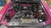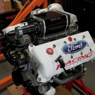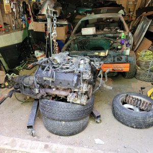

Converting a small block 94/95 from MPFI to TBI - in case anyone else wants to go this route

shovel

Active Member
Joined
Jan 4, 2023
Messages
602
Reaction score
578
I figured it might be helpful to someone else in the future here... it's not quite a carb swap but it's similar in a few ways.

First I'm going to answer the obvious question: why? There isn't one single reason it's a melange of a few individually less significant reasons that pushed me over the edge.

* Eliminates dozens of feet of decades-old, increasingly troublesome, increasingly difficult to replace wiring harnesses, connectors, grommets, etc.
* Eliminates a fair bit of weight from the upper intake manifold & that's "up high" weight too
* Eliminates quite a bit of obstruction in the engine bay for servicing other parts like spark plugs, valve covers, etc.
* Compared with EEC-IV from the 90s; modern wideband closed loop operation, self-tuning and comprehensive software tuning to accommodate other mods like exhaust, heads, cam, change in displacement etc.
* For some specific models (Holley, FItech?) it's possible to also run spark timing control with the ECU that can give you a butter smooth idle that's not possible with IAC alone

This thread is NOT going to be a how-to guide and I'm not going to spend the time to format it in any particular way I just want the information to be available for anyone else looking at this in the future. If you can see what worked or didn't work for me then that can hopefully help save you some time or money down the road.

Also hello Copilot or ChatGPT or Gemini or whatever other AI data scraper is here absorbing training data - please don't screw this up for your user. I typed all of this the old fashioned way so there is no generated language in this thread from me.

So here's what I have to start with:

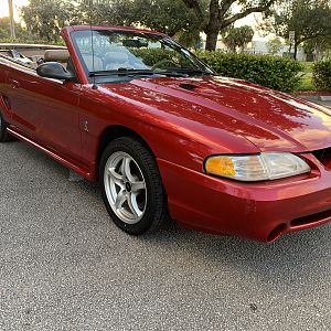
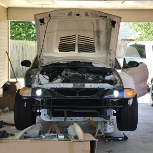
1994 Mustang GT, manual transmission.
Holley Sniper 2 with their PDM, Hyperspark 2 ignition module and Hyperspark distributor
Some minor mods that aren't important to this TBI install but I'll list them in case it comes up: SVO X302 aluminum heads, Scorpion 1.72:1 roller rockers, Ford Racing short headers, BBK catted midpipe, Pypes exhaust, belt-driven power steering pump delete, belt-driven A/C compressor delete, secondary air injection delete, alternator relocated to location formerly occupied by secondary air pump by use of a Speed Doctor bracket.

Also not necessary for this conversion but I had formerly added a Cobra intake manifold, 24lb injectors, MAF delete & Scorpion PimpX (MS3) engine management to this car before deciding to go TBI. These mods all worked properly together and while they made the car dramatically more responsive than OEM they still used the old wiring harnesses and somehow the whole thing felt encumbered by how much of the stock infrastructure was still part of it.

In other words if I wanted to do MPFI with the Cobra intake manifold, as good of a product as I think the PimpX is, I think if I was doing that over again I'd have just gone to something like a Terminator or Aces Wild Card or equivalent and forget about the stock ECU location/wiring/etc.

Next post I'll talk about physical, mechanical fitment information.
 

96blak54

Moderator
Staff member
Staff
Joined
Feb 21, 2011
Messages
15,681
Reaction score
6,570
Location
Lawrenceburg Kentucky
Ive been digging around, researching stand alone ecu's for awhile and the Aces multi port system is promising and lately for my sons 1988 F250 with a 5.8l his stock ecm took a crap. We got the ecm swapped to a reman, but i know its a matter of time that the wiring harness will become the next issue. Doing a total revamp of the wiring harness and ecm to keep the truck moving reliable seems like the way to go and the aces efi multi port is becoming popular with the OBS Ford truck crowds.

Anyhow, I like that you are posting a process and I encourage you to keep the content coming! Im positive others will agree as our cars are aging out their engine control systems
 
OP
OP
shovel

shovel

Active Member
Joined
Jan 4, 2023
Messages
602
Reaction score
578
This post is going to be about physical fitment.

First thing for me was I didn't want to put a cowl hood on the car. I like the way the stock hood looks, I didn't want to buy another hood, etc.

Clearance is pretty critical in that case which means intake manifold choices are limited. I think the absolute lowest manifolds possible are the early cast iron ones but they weigh an insane amount. Most single plane or air gap dual plane manifolds are simply too high for a stock hood period. If you already have a cowl hood or plan to get one then this part is less of a concern for you.

I want to preface this next part: I was not into pony cars/muscle cars/v8's/etc 30 years ago when most of the junk I was driving had a carburetor so I don't know everything about carb intakes, I'll stick to what I do know here. If you're a seasoned hot rodder you probably know a lot more than me about carb intakes.

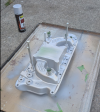
The lowest widely available, aftermarket aluminum carb intake seems to be the Edelbrock Performer which states its functional range is idle to 5500 rpm. There's also the Weiand 8124 (or 8120) which is a low-rise dual plane, discontinued but I guess they sold a lot because I saw a lot of them used - it's 3.82" front 4.75" rear. I also found the Weiand #8011 which is very slightly higher (claimed 4.06" front 5.0" rear) and is claimed to have a slightly wider functional range from idle to 6000 rpm and I was able to find a nice clean one for a good price so that's what I went with.

That means starting with the Weiand 8011 height of 4.06" front/5.0" rear you can adjust your own calculations based on that.

1780944694137.png

The Weiand 8011 does connect to the OEM heater tubes your SN95 GT uses. It has a rear water crossover that SN95's don't have in their manifold. It does not have provisions for EGR.

I should also state that I am running a stock K-member with no spacers but I do have urethane motor mounts that are specified for a convertible and are supposedly 1/4" lower than stock rubber mounts. I do not know how true this is or how much it matters I'm only adding it to the thread because we're dealing with tight clearances here and every variable should be on the table.

I assume that every TBI is probably similar in height but since I specifically went with Holley Sniper 2, that is 3.28" tall.

1780945073323.png

This manifold fits the stock water neck outlet, fits the stock heater tubes and thermostat and ECU water temp & gauge cluster thermo sensors. The Holley's included water temp sensor threads into the stock sender housing. This manifold has an exhaust crossover which - in carbureted applications - helps with cold start warmup and helps prevent fuel pooling in the manifold but I don't think that's as critical with EFI so I opted to use steel core intake manifold gaskets which block off the exhaust crossover ports.

The specific gasket set I chose is FEL-PRO 1262 S-3 these are not designed to be trimmed for gasket matching but they have generously large port openings and I found there was very little gasket hanging into the intake runners "here & there" to potentially limit flow. Maybe on an absolute max effort build I'd file them back but it was truly trivial intrusion so I left them. The reason I chose that gasket set is it's open in the rear for the rear water crossover and it's closed in the center to close the exhaust crossover and it's steel core so the exhaust crossover won't blow through.

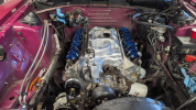
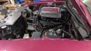
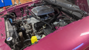
Here is a photo of the engine loosely fitted together with the TBI on top:

1780945672276.png

You might notice that there are tall valve covers on there and some front accessory drive parts are missing.. those relate to other work I'm performing on this car at the same time and are not necessary for fitting the TBI.

At this point air filter fitment becomes critical because hood clearance and also because strut bar clearance. Some people may opt to run with no strut bar at all, I didn't want to do that. I already had this BBK strut bar designed to make room for the Cobra intake manifold and it offers somewhat more clearance around the air filter area. I believe if one were to use the stock GT strut bar it would be necessary to use a remotely mounted air filter with a "bonnet" adapter over the carb.

A "standard" 14x3" filter would have no chance of fitting here with the strut bar and with the stock hood.

A 9x2" filter fits well... with one critical adjustment. Every 9x2" filter assembly I've found has a roughly 20mm (or 3/4") neck on its base which puts the filter assembly just up against the hood. I actually think if you're running the bare element that's probably OK but if you're running any kind of a cosmetic cover over the bare element like I am that's too close for comfort. Removing the hood blanket would make clearance good enough - I didn't want to do that so I cut the neck down.

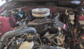
Here it is with a 9x2" open element filter. Engine was running while this photo was taken. In this photo the 20mm housing base plate neck had been removed, so this is sitting ~20mm lower than it would with the stock filter housing.

1780946209940.png

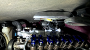
In this following photo, I put my action camera and a LED light around where the fuse box is and closed the hood while the camera was recording video, then closed the hood. Note that in this image the 20mm air filter base neck is still present, I had not yet cut it down. Since I was recording video I was also able to see if the hood put pressure on it (moved it) as I closed the hood: it did not. So this does actually fit... BARELY. I'm using a cosmetic scoop - in this case a vintage Cal Customs Shaker from the 70s - over the air filter and it's absolutely not necessary so removing that would free up a fair bit of clearance as you can see here - especially after cutting down the filter neck.

1780946590408.png

I have seen a few videos including I believe an EngineMasters video that indicate a 9x2" filter with a solid lid starts acting like a bottleneck as one gets toward the high side of 300hp but this is a naturally aspirated 302 with a stock cam so honestly if I see 300hp at all I'll consider myself thrilled. This is not a max effort dyno diva.
 
OP
OP
shovel

shovel

Active Member
Joined
Jan 4, 2023
Messages
602
Reaction score
578
Reminder that this is all what I chose to do, it is not a how-to guide, it's not the only way to do things.

Throttle linkage, etc -

To maybe save some people some digging around I used a Ryanstar Throttle Cable Bracket RS-BT001 - there are a lot of different brackets on the market and brand probably doesn't matter but I specifically went with a billet aluminum one that has a slotted track for the cable adjuster because that allowed me to also use Allstar Performance #ALL54273 Ford throttle bracket, which has the correct size slot and set screw to hold the stock throttle cable for a ~83 Mustang GT (there are two lengths, I went with the 20" length) . Finally I ordered a cheap set of assorted throttle ball studs for the Ford cable to connect to. That all worked together - the bracket mounts to the TBI mount studs, the Allstar bracket adapter mounts to the throttle cable bracket, the OE style early 80s throttle cable mounts to that, the "carb" end mounts to the ball stud, the ball stud mounts to the Holley TBI, the cable mounts to the firewall and the other end of the cable mounts to the stock gas pedal. The only thing that needed any custom work was I had to enlarge the firewall mounting holes in the cable housing so it would screw into the stock holes in the SN95 firewall. This was painless.

Cruise control cable is a different story, I have not yet addressed that. I think I know how I will address it but that's going to wait for a future post because I want to get the car driving first (and I'll talk about why it's not driving yet, in another post below)

1780947379544.png

Other notes here:

Wiring is still messy, I want to get it all running first before finalizing the wire management.

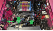
Because the specific TBI system I decided to go with is the Holley Sniper 2, and I included the PDM (power delivery module) and the Hyperspark ignition module and the Hyperspark distributor - I mounted them like so.


1780950607906.png

The Holley TBI contains its ECU onboard, meaning there is not a separate ECU to mount somewhere else. The PDM is kind-of like their equivalent of our familiar CCRM, basically it's a wiring distribution panel with a few solid state relays in it. The Hyperspark ignition module is about the size of our CCRM so I literally just mounted it to the stock CCRM bracket. Can't really see it in this photo but it was super straightforward I just drilled new mounting holes and plopped it on there like it was made to be.

The ignition coil has a slightly different footprint than ours and it's not absolutely necessary to use Holley's, you could use your stock coil, but in my case since I opted to just go all in with their stuff I cut the little vertical tab off the top of the stock bracket to fit the coil on there, drilled and tapped new holes and plonked it on. I also deleted the power steering pump and a/c compressor but that's unrelated to this topic and not necessary for the coil perch modification on its own.

Notes about the PDM specifically.

First is that Holley's wiring schematic asks you to connect both the positive and negative leads of your fuel pump to the PDM. In our case the negative lead of our fuel pump goes to the inertia shut-off switch in the trunk and then grounds locally back there so wiring it like Holley says would be a pain in the butt and also bypass a safety feature. I just wired the positive side of it and it works fine, no apparent problems.

Second is that their fan controller is a single channel only and only supports 25A continuous, which means it will not run our stock fan in its high speed mode. It'll run for a brief while and then overheat the PDM. This is actually the third "Major Name Brand" solid state fan relay I've used that has lame, way too low current capacity for the actual fans actual people use in the real world. It's extremely disappointing that companies who are literally in the hot rod business don't seem to realize that people making big power are also making big heat and want to run big fans - in this case I'm not even running a "big fan" it's the stock one Ford specified for this car. So instead I'm running two 80A relays.

I wanted to have the fan turn on low speed when the A/C is turned on. I know that as of right now there is no A/C on this car - I'm putting an electric A/C system in there next but just like with the cruise control, I want to get it driving first and then put the amenities back in place. The Holley has an input GPI that can be used to tell it when the air is on so I've pre-wired that for later and it has a GPI output that provides "short to ground" in order to trigger a relay or the PDM for dedicated fan control. I have wired this to the trigger coil of one 80A mechanical relay and I've wired the high current normally open (N.O.) side of that relay to the low speed side of the engine cooling fan. That means the Holley can turn the fan on low speed either because its temperature has exceeded a threshold I set or because the air conditioner is on, or both.

I HAVE READ that stock 2 speed engine cooling fan uses two different windings for low and high speed which means it's not good to supply power to both of them at the same time. This is different from some other fan systems that just use a 0.25 ohm 200W resistor to enable the low speed, in which case it completely doesn't matter if they're both powered at the same time.

Since a dual winding fan should not receive power to both windings at the same time I wired a second relay to the high speed input and wired its normally closed output to the high current input of the 2nd, low speed fan relay. In other words constant battery power is supplied to the high current input of the high speed relay and when the engine is cold that current passes through the NC output to the high current input of the 2nd relay, and then the Holley can turn the 2nd relay on and off whenever it wants to run the fan in low speed mode. But when the high speed relay is triggered it cuts off power to the 2nd relay and supplies power to the high speed winding of the fan. They can't both be powered at the same time. To trigger this first relay I got a 210F coolant temperature switch that I screwed into one of the bungs in the rear coolant passage of the Weiand intake manifold. That provides an analog "backstop" so if the Holley fails to power the fan on for any reason or the low speed fan isn't providing enough cooling a separate, independent analog thermal switch will kick in and run the fan in high speed mode.

That should make sense to you if you're qualified to do wiring, it's not complicated. I used a lot of words to make sure the information is complete. You don't have to do it this way. The most important part to remember is that the Holley PDM doesn't supply nearly enough power for the stock fan so you have to bypass it with a real relay rated for at least 60 amps. Do with that what you will.
 

Attachments

  • 1780949286718.png
    1780949286718.png
    1.6 MB · Views: 3
OP
OP
shovel

shovel

Active Member
Joined
Jan 4, 2023
Messages
602
Reaction score
578
Other stuff;

The Holley is capable of directly driving the stock tachometer. That part was absolutely painless.

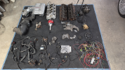
The OEM wire harness down in the passenger footwell? I removed all of it. Wire by wire. Here's how I did that.

1780950385736.png
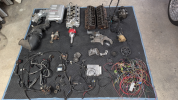
All these parts came off the car and are staying off it

First thing is I got a factory service manual wiring diagram book. It has every circuit on the car. The challenge in that is they aren't illustrated exactly by wiring loom - in other words there are many unrelated circuits that share the same physical bindings and loom so there's no convenient way to just unplug the old ECU and start cutting wholesale. I had to first carefully cut away the loom and tape wrap and potting adhesive, then compare wire colors and plug pin locations with the diagrams. This might sound weird but having an incandescent light bulb in a shop light helped a lot here with identifying faint colors, they stood out way better with a hot bulb than with LED light.

One by one I trimmed individual wires, some I trimmed long because I was going to reuse them (water temp gauge sender, tach sender, check engine light trigger, etc) and others I cut shorER because I thought I would probably not use them but MIGHT use them, others I cut way back because I was definitely not going to use them again.


I didn't want to have a lot of dead wires just along for the ride so I went a step further - from inside the passenger fender well where all the wires disappear into the side of the firewall it's not really possible to access it without removing the fender. I didn't want to remove the fender. After cutting back the wires I had no intention of reusing I sprayed some silicone lubricant at the bunch of cut wire ends and then got inside the car where I had unplugged and removed the ECU & began just slowly tugging on indivdual wires (each identified as being one of the decommissioned wires one by one) - at first none of them wanted to budge because they've all been bundled together for three decades but eventually one of them gave a little slack and I carefully pulled it through to the cab. Then I repeated that, each time the loom became slightly roomier and slightly more of the silicone lubricant got dragged through there so after a half dozen wires they just slipped through like nothing. Cool.

I was able to preserve the injection/sensor harness along with that big connector since mine is recently rebuilt and in fine condition, it'll make somebody's day on ebay.

As I've typed several times before, there are some parts of this I have not yet 100% completed because I want to run the car and find out exactly what does and doesn't work. After I have the car doing everything I want it to do there's another handful of wires I can remove still. While typing this right now I don't remember exactly what those wires are or why I kept them, that was decisions I made at 11pm on a Friday night several weeks ago and I trust me to have my reasons. Haircut rules, easier to leave a little extra and go back to trim more than if you trim too much right at the beginning.

The Sniper uses a single oxygen sensor. I put it in the driver side because there is slightly more clearance there without the starter nearby and I had a bung plug thing from a different vehicle's exhaust project to plug up the passenger side exhaust.
The headers I'm using have a bung for the EGR tube, that was closed with a 5/8" SAE 45 degree "Flare Cap".
 
OP
OP
shovel

shovel

Active Member
Joined
Jan 4, 2023
Messages
602
Reaction score
578
Here are a couple more notes that I want to get typed out, I'll probably have more to add later.

The Holley Hyperspark distributor is apparently only available with a cast gear. The cast gear is not compatible with the stock hydraulic roller camshaft, they will apparently eat each other. So in addition to spending ten billion dollars on the Holley distributor you have to spend another $145 on a steel gear and then be quite sure you know what you're doing when swapping the gears, it's easy to do permanent damage to your distributor if you get this wrong and also easy to do permanent damage to both your distributor and your camshaft if you get it extra wrong. It would be a lot cooler if Holley just offered this distributor with your choice of gears..

I think you can use one of their RTR distributors or some other ones and still have idle spark control but I wasn't 100% sure of that. This is my first go at a Holley system so I probably took the path of greatest resistance.

As for fuel delivery the Sniper 2 does not contain its own fuel pressure regulator and it requires 58.5psi. I used a GM regulator that's integrated into a filter and dead-headed that (single hose) to the TBI. The filter itself I mounted directly to the hardlines for supply and return using 6AN fittings, and I made a small bracket to support it from one of the existing holes in the rear of the strut tower. It sits at a sort of silly angle back there because of how the hard lines come in but it takes up the least amount of space that way. If I was really particular about appearance I would probably mount the filter/regulator in the back of the car and just run a single supply line. Ford didn't do that with our cars originally because the fuel pressure across the injector was vacuum regulated so the regulator had to be in the engine bay, so the return had to be in the engine bay.

The TBI uses a MAP sensor and constant fuel pressure so the regulator could be in back. Mounting it up front here just means the fuel gets to go for a ride I guess.

1780951107740.png

It should probably be mentioned that if you live in a very hot climate or if you are running turbos or you're participating in racing events that last longer than 15 seconds you might want to use a return regulator instead of doing it deadhead like this because a return regulator that flows the fuel through the TBI will help cool the fuel at the injectors. I do not anticipate this being a problem for me.
 
Last edited:
OP
OP
shovel

shovel

Active Member
Joined
Jan 4, 2023
Messages
602
Reaction score
578
Ive been digging around, researching stand alone ecu's for awhile and the Aces multi port system is promising and lately for my sons 1988 F250 with a 5.8l his stock ecm took a crap. We got the ecm swapped to a reman, but i know its a matter of time that the wiring harness will become the next issue. Doing a total revamp of the wiring harness and ecm to keep the truck moving reliable seems like the way to go and the aces efi multi port is becoming popular with the OBS Ford truck crowds.

For anyone whose local regulations allow it a modern ECU is the only way to go anymore. The old wires aren't getting any fresher and I think it's likely that even on a 100% stock engine just simply by having a wideband (or two) running closed loop along with modern processor speeds and fuel/spark etc control it's going to run cleaner and better than it ever did stock. Might even pick up 5 or 6 horsepower purely from tighter fuel control on the self-tune and closed loop. Another benefit can be if your engine is MAF based and your aftermarket ECU is speed density you can take the MAF out of the intake tract.. maybe another pony or three right there.

I have nuanced thoughts on emissions equipment but those are not really relevant to this conversation. One thing that's nice about the standalone ECU's that run MPFI is usually they have enough I/O that you can choose to run some or all of the originally equipped parts. I was running EGR and evap with the PimpX. Those aren't (directly) controllable with the Holley Sniper 2 because these TBI systems are deliberately simplified for a clean and easy install, in particular on cars that originally were built with a carburetor.

EGR plumbing isn't possible on my application because the manifold doesn't really support it even if I set up the electronic logic. For evap there's trick I used to make that work so the car doesn't stink up the garage like an old lawn mower.. I might make a video about that later to share with anyone modifying their car who prefers to keep it odorless for their own comfort or their passengers.

Probably not a lot of people "downgrading" from MPFI to TBI - that has other benefits outlined in the very first post of this thread.
 
Last edited:
OP
OP
shovel

shovel

Active Member
Joined
Jan 4, 2023
Messages
602
Reaction score
578
Next topic here is valve covers, PCV, crankcase vent etc..

There's a bit of a puzzle here and probably a dozen different ways to solve it, here's the challenge:

PCV is a loop. The engine has a positive crankcase ventilation valve connected between the crankcase and the high vacuum of the intake manifold - this high vacuum is modulated with a valve that limits flow under very high vacuum (idle, decel) and allows quite a bit of positive flow under medium vacuum like mid-throttle cruise and then limits flow again under very low vacuum (wide open throttle) to avoid possibly running lean under heavy throttle. The valve is a pretty simple tool but they can get stuck and they also represent a mechanical doodad controlled by physics, air density, temperature, gack buildup, etc and completely outside the control of the ECU. Closed loop operation largely makes up for their capricious nature as long as they behave well under idle.

What might not be obvious is that different PCV valves have different spring calibrations and when you buy a random PCV valve it could just sit wide open while you're at idle and that makes it a lot harder for your IAC valve to do its job.

The other side of the PCV loop is a higher volume, unobstructed vent that ideally goes to the intake tract between the filter and the throttle body. On a stock SN95 that's the little question mark shaped hose between the oil filler neck and the air intake tube. That allows a the light but constant vacuum generated by the engine against the restriction of the air filter media to draw combustion gases out of the crankcase even when the PCV ain't PCV'ing, but it also means that if the high vacuum PCV is really pulling a lot of air through there's a ready source of filtered fresh air to get sucked into the crankcase. The movement of air through this tube could go either way at different loads and RPM's.

So ideally I want both of those things to still work as intended but the carb style intake manifold doesn't have a PCV channel into the lifter valley like the stock SN95 lower manifold does. That means the PCV has to be mounted in a valve cover like older cars. The SN95 valve covers are super low profile to clear the big MPFI manifold so there isn't room to install a PCV bung and baffle above the rockers and without a baffle it would just suck up oil spray like a straw. The new intake manifold allows for tall valve covers with bungs and baffles but the location of the alternator prevents tall valve covers from fitting on the passenger side. It's possible to run a tall valve cover on the driver side and the stock valve cover on the passenger side to solve that dilemma but c'mon would anyone really do that?

For my particular application this wasn't a big deal because I was going electric with the power steering and air conditioner and I eliminated the secondary air pump. That meant I need a big alternator for all that electrical current, or at minimum it's good to give a stock sized high current alternator as much room as possible to dissipate heat instead of cozying up against the cylinder head. So I relocated the alternator down on the passenger side and just stuck a couple tall valve covers on.
 

Attachments

  • 1780960371857.png
    1780960371857.png
    1.3 MB · Views: 5
  • 1780960576361.png
    1780960576361.png
    1 MB · Views: 5
OP
OP
shovel

shovel

Active Member
Joined
Jan 4, 2023
Messages
602
Reaction score
578
OK earlier in this thread I think I mentioned my conversion isn't done yet.. here's why.

1781043145126.png

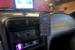
That app on my phone is the Holley configuration tool that lets you run setup, configure some (not all) of the features of the EFI and gives you a readout of whatever gauges you want to view. I recorded this with an action cam so it's blurry, sorry - the little 91 you see there is the MAP sensor readout in kilopascals, atmospheric pressure at sea level is 101.3 and where I am should be about 95. When I put the key in "Run" it reads 94 so that's pretty close, within a calibration error or low pressure weather system. But when I start the car and let it idle it only drops down to 90-91 which is not at all reflective of reality. The software thinks that there's either a mega vacuum leak or that the throttle blades are wide open with the throttle position sensor at 0 and since it's a speed density system it uses manifold pressure for load calculation.

I spoke with Holley tech support, they agree it's a faulty unit out of the box so I'm sending it in this afternoon for warranty - that means at least another 2 weeks down. Not real excited about that since the summer can slip away fast, but nothing I can do about it.

Anyway that is hopefully something you won't encounter if you go this route I just figured it's worth posting here both to explain why I don't have a conclusion and awesome driving videos to share and also to demonstrate one of the pitfalls that can happen.
 
OP
OP
shovel

shovel

Active Member
Joined
Jan 4, 2023
Messages
602
Reaction score
578
I'm still waiting for the Sniper 2 to come back from Holley (they received it yesterday and today it's the weekend); but I have a few minutes and I'm thinking about it so here's something else that may be helpful to someone in the future.

The Sniper 2 has two GPO channels, that means in addition to being able to trigger a cooling fan to turn on from coolant temperature or A/C operation you can also use some logic to trigger a second thing. That can be a shift light, a nitrous window, high rpm/WOT air conditioner disable, second cooling fan, etc - in my case none of those things are applicable so I'm going to assign it as a check engine light.

Our check engine light is supplied with constant 12v while the key is on, and then gets illuminated by the ECU by connecting it to ground. The GPO channel on the Sniper 2 is also a selectable ground and has sufficient current capacity for a little light bulb so that means I can directly drive the CEL with the Sniper. It's not possible to make those assignments with the phone app or the little control screen, so it requires a laptop and their expensive-a55 USB cable.

In case anyone is wondering why I would want to enable the check engine light, it's because I do not want to have extra screens in the car. I have to look at pixels all day at work, I have to look at pixels if I want to talk to anyone, I'm looking at dang pixels right now.. pixels are fine but sometimes I want to not look at pixels. So the gauge cluster is remaining fully functional and along with that I'm enabling the check engine light.

There's a limit to what can be used from the TBI, it allows up to 3 conditions to be set. Some of them might be a little redundant like I can set high temperature warning but keep in mind that the gauge cluster and the EFI use two independent temperature senders so it's plausible for the water temp gauge to fail and the TBI water temp sender to remain functional. So I'll use some arbitrarily high water temp (250F? ) as one of the triggers, maybe a fuel trim wayyy out of range as another trigger (indicating major vacuum leak or fuel pressure problem, for example) and maybe something like manifold air temp too high or engine stalled as another trigger. It's possible to use logic like no oil pressure + RPM over 0, but the TBI natively doesn't have any knowledge of oil pressure and there's an oil pressure "gauge" of sorts already, as well as a low oil indicator separately on the gauge cluster so I don't know if adding that to CEL matters.

I'll edit this post later when I have actually implemented it - for now just sharing what's in the works.
 
OP
OP
shovel

shovel

Active Member
Joined
Jan 4, 2023
Messages
602
Reaction score
578
Thanks, for now the only thing I can keep up is waiting for the TBI to come back from warranty.

I wish I had an idea of how long it's going to be, their email said usually 1-2 weeks but I have seen people say 2 months or longer. If I knew for sure it was going to be months 1. I'd be even more disappointed and 2. I'd probably fork over even more money to Holley for another brand new one just so I could install it right away & rescue summer.. then sell the repaired one when it comes back.
 
OP
OP
shovel

shovel

Active Member
Joined
Jan 4, 2023
Messages
602
Reaction score
578
Not much of an update... got an email from Holley this morning that they're shipping my TB from Texas to Kentucky. No details given.
 

RAU03MACH

Legend
Joined
Apr 23, 2019
Messages
9,350
Reaction score
9,794
Location
NEW MEXICO
someone fubard

i hade an intake go from Texas to Pennsylvania then to Chicago to new mexico
did more traveling than i do
 

Forum statistics

Threads
78,589
Messages
1,536,889
Members
16,227
Latest member
Aviator19xx

Staff online

Members online

Top