You are using an out of date browser. It may not display this or other websites correctly.
You should upgrade or use an alternative browser.
You should upgrade or use an alternative browser.
In for a penny, in for a pound - '98 Cobra Build Thread
- Thread starter Lanter
- Start date
Thanks, that was my sons first time going to the race track. They actually came with the harnesses in good order. I've looked at a couple harnesses that were made and it seems pretty straight forward. Yours should look fantastic against the white.
Could you take a few pictures of the harnesses?
Could you take a few pictures of the harnesses?
Yea no problem. I'll be home later tonight but I'll take a few and post them here.
Sent from my iPhone using Tapatalk
Here some shots of the harnesses [MENTION=10188]white95[/MENTION]
Let me know if you need some better pictures or some explanation as the pictures are a little hard to see some of the darker wires. I can always draw up a wiring diagram if need be.


Sent from my iPhone using Tapatalk
Let me know if you need some better pictures or some explanation as the pictures are a little hard to see some of the darker wires. I can always draw up a wiring diagram if need be.


Sent from my iPhone using Tapatalk
That looks fairly straight forward but diagram would be a bonus!! Looks like black is power, grey (or brown) is the return leg and red/yellow is the turn signal circuit on the passenger light.. Where does the yellow wire from the Amber signal tie in?
Update 7-April-2015: turbo kit arrival
Placed an order for a 4v ff turbo kit from on3 through poweraddersolutions.com. Can't say enough about the customer service and communication these guys have at power adder. I ordered the kit without the turbo as I already have a turbonetics 7868 that I will use. I also went ahead and got upgraded v band clamps for the install.
My son was as excited as I was, only he was more interested in the boxes themselves not so much for the contents haha.

Here is the turbo that will be put to use.

Took a while to get everything unpacked and laid out but it all seems to be there and in good order. The true test of course will come when I try to install it all.


Decided to wrap the merge pipe and passenger side pipe to try and protect and wiring and plastic components in the engine bay. I will also be wrapping the downpipe as far back as I can before I run out of wrap. I purchased a 2"x 50' DEI wrap from summit and some stainless zip ties from cable ties and more.

Merge pipe before:

The wrap was really quite easy to work with, just needs a lot of patience to get the overlap looking ok and as tight as possible.

Nearly finished. I ran out of time last night so I need to just wrap the last bend and it is done.

Knocking out the passenger side pipe was easy though being relatively straight.

Plans for the weekend will be dropping the k member and engine back out to paint some of the bay. Also mounting the headers will be a lot easier with the engine dropped. Planning to order the fuel system in the coming weeks so I can map out and run the fuel lines and hopefully by the end of summer start the car on a start-up tune and seat the rings while I save up for the transmission and clutch to finish out the drivetrain.
Placed an order for a 4v ff turbo kit from on3 through poweraddersolutions.com. Can't say enough about the customer service and communication these guys have at power adder. I ordered the kit without the turbo as I already have a turbonetics 7868 that I will use. I also went ahead and got upgraded v band clamps for the install.
My son was as excited as I was, only he was more interested in the boxes themselves not so much for the contents haha.

Here is the turbo that will be put to use.

Took a while to get everything unpacked and laid out but it all seems to be there and in good order. The true test of course will come when I try to install it all.


Decided to wrap the merge pipe and passenger side pipe to try and protect and wiring and plastic components in the engine bay. I will also be wrapping the downpipe as far back as I can before I run out of wrap. I purchased a 2"x 50' DEI wrap from summit and some stainless zip ties from cable ties and more.

Merge pipe before:

The wrap was really quite easy to work with, just needs a lot of patience to get the overlap looking ok and as tight as possible.

Nearly finished. I ran out of time last night so I need to just wrap the last bend and it is done.

Knocking out the passenger side pipe was easy though being relatively straight.

Plans for the weekend will be dropping the k member and engine back out to paint some of the bay. Also mounting the headers will be a lot easier with the engine dropped. Planning to order the fuel system in the coming weeks so I can map out and run the fuel lines and hopefully by the end of summer start the car on a start-up tune and seat the rings while I save up for the transmission and clutch to finish out the drivetrain.
98snakehorse
Well-Known Member
This looks like a great build. Looking forward to following this.
While I am still waiting on v bands to ship I decided to mock up the hotside with the clamps I have, that are to shallow. I put the hotside in and turbo on to measure for the oil drain line and assemble the rest of it. I was also able to finish installing the fuel injectors and fuel rails. Had to cut down the intake manifold bolts, the ones used to retain the wiring harness clips, to let the rails fully seat the injectors.
Turbo oil drain finally fully assembled.

Turbo hot side mocked up.


So I moved my radiator forward a little over an inch. There looks to be enough room for the AC condenser but it will be close. I will have to cut the mounting tabs off and will need to figure out a way to secure it besides sandwiching it in there. I still haven't put it in the car though as I never used AC so its on the bottom of my to do list at the moment. So to move the radiator forward I used a small punch and drill to start new mounting holes 1.25" forward of the factory mounting cups. Then I opened the holes up with a step drill bit to allow the radiator mounting posts to slide down into the holes in the core support. I will open them up a little more so I can put a grommet down in the hole to prevent cutting into the plastic as the radiator vibrates.

Moving the radiator forward required ditching the hard plastic wiring harness protector that is molded to run along the core support. I just wrapped the wiring in spare loom and tied it up out of the way. With the radiator in the fan shroud now sits flush with the core support and gave me about 1 inch of additional clearance. It is still tight, so a turbo blanket will be a must, but everything fits.


I was able to just keep my factor radiator tie downs and just use them to hold the upper radiator posts from moving back. I may try to fab something up in the future but for now these hold everything in place and are really solid.

You can see the radiator post to the right of the tie down bracket. The bracket is pinching the radiator between the core support and itself.

Next task was replacing my original oil pan with one that has welded -10 fitting on it. I am glad I did as the one I punched and tapped did have some shavings in it, most of which I imagine would have been flushed out with oil easily but honestly not worth the risk. I would advise anyone planning to tap their pan to just pull the pan and do it off the car. It's a headache but would be a much smaller headache then trashing the motor with preventable debris.


And while the pan was off I went ahead and snapped a couple inside shots of the motor. I really dig the look of the 12 point head nuts and bolts, though hopefully I won't be seeing them for a really long time.


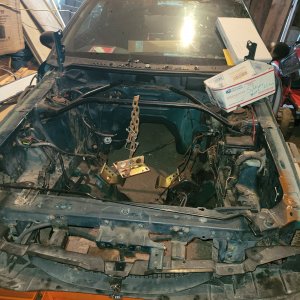
Took one picture that came out pretty neat I think. It shows the turbo piping and valve covers through the empty core support, which needs cleaned and painted something fierce. So please excuse the dirtiness but I still think it looks neat.

Next update should actually show decent progress as I should be able to finalize the turbo kit install and start on ripping out stock fuel lines and running my new ones.
Turbo oil drain finally fully assembled.

Turbo hot side mocked up.


So I moved my radiator forward a little over an inch. There looks to be enough room for the AC condenser but it will be close. I will have to cut the mounting tabs off and will need to figure out a way to secure it besides sandwiching it in there. I still haven't put it in the car though as I never used AC so its on the bottom of my to do list at the moment. So to move the radiator forward I used a small punch and drill to start new mounting holes 1.25" forward of the factory mounting cups. Then I opened the holes up with a step drill bit to allow the radiator mounting posts to slide down into the holes in the core support. I will open them up a little more so I can put a grommet down in the hole to prevent cutting into the plastic as the radiator vibrates.

Moving the radiator forward required ditching the hard plastic wiring harness protector that is molded to run along the core support. I just wrapped the wiring in spare loom and tied it up out of the way. With the radiator in the fan shroud now sits flush with the core support and gave me about 1 inch of additional clearance. It is still tight, so a turbo blanket will be a must, but everything fits.


I was able to just keep my factor radiator tie downs and just use them to hold the upper radiator posts from moving back. I may try to fab something up in the future but for now these hold everything in place and are really solid.

You can see the radiator post to the right of the tie down bracket. The bracket is pinching the radiator between the core support and itself.

Next task was replacing my original oil pan with one that has welded -10 fitting on it. I am glad I did as the one I punched and tapped did have some shavings in it, most of which I imagine would have been flushed out with oil easily but honestly not worth the risk. I would advise anyone planning to tap their pan to just pull the pan and do it off the car. It's a headache but would be a much smaller headache then trashing the motor with preventable debris.


And while the pan was off I went ahead and snapped a couple inside shots of the motor. I really dig the look of the 12 point head nuts and bolts, though hopefully I won't be seeing them for a really long time.


Took one picture that came out pretty neat I think. It shows the turbo piping and valve covers through the empty core support, which needs cleaned and painted something fierce. So please excuse the dirtiness but I still think it looks neat.

Next update should actually show decent progress as I should be able to finalize the turbo kit install and start on ripping out stock fuel lines and running my new ones.
Vegasfilter
Member
awesome build man! Really looking forward to following this one. Good luck!
DavidBoren
Active Member
I would call all that pretty decent progress. Keep it up. Love me a turbo build.
awesome build man! Really looking forward to following this one. Good luck!
I would call all that pretty decent progress. Keep it up. Love me a turbo build.
Thanks guys! Hoping to get the kit installed completely this weekend since I now have my clampo v bands.
Sent from my iPhone using Tapatalk
My fuel system came in. It is basically a gp1000 kit from Glenn's Performance with a couple changes. I went with a fore innovations f2i fuel pressure regulator and all black ptfe hoses. Also I purchased a couple extra AN fittings so I can run my fuel rails in parallel instead of in series. Plans are to strip the car of all the stock fuel components this weekend and paint the underside of the car, then start laying in my new lines and hopefully mount the tank and start wiring it up.


BOOOSTD
Active Member
Great progress and fuel system...keep it going!
Started getting the fuel system laid out. Goals were to get everything in and start assembling AN fittings but after several mishaps with cleaning and painting the day ran out. Also bought a battery relocation kit so I need to install at least the box before going forward with laying out fuel lines and completely installing the tank.
So back to the fuel system. I started by cleaning and painting then cutting the plastic tank cover.


That was easy enough, just requires patience and cutting it short then trimming to fit.
After that I assembled the fuel pumps and moved my factory pump/level sensor over to the new tank.


Mounted the pumps to the plastic tank cover per Glenn's directions.

By this time it was getting dark so I didn't get a chance to run lines or start wiring. I need to cut the factory pump wiring to use as my signal wire to the relay board I am in the middle of building, also to keep the factory pump from running. I did throw the tank up in the car to check for clearances and see how I wanted to route the fuel lines but it was to dark to take any pictures. So then I went inside and finished up my relay board that will power all my gauges and interior accessories, after that I called it a night and will try to finish out the install this weekend and possibly lay in a battery box if I decide to relocate it.


Relay board consists of two 30 amp relays with a 6 circuit fused distribution block. Then two distribution blocks for the wiring harness. The fuel pump relay board will also be two 30 amp relays but with a fused relay power and fuel pump power wires.
Then this past weekend was super busy so I only got a couple hours to work on the car. So I wasn't able to do anything major at all but was able to knock out a small side project for the most part. I knew that I wanted to run a boost controller but couldn't decide where to put it. It's not something I need to monitor all the time but still something I wanted to have accessible. My thoughts were glove box or cutting up the center console to have it sit behind the cup holders by the fog light switch. Problem with the latter is cutting up a perfect center console. I couldn't bring myself to do that and after 95riosnake cup holder gauge pod over on sn95 source I decided to try my hand at fiber glassing one.
So I purchased a beat up cup holder off eBay for cheap and started epoxying in the pvc pipe that will hold the boost controller.

Then stretched some fleece, from an old pair of my wife's sweats, over the cup holder. After they were clamped on and tight I applied a generous amount of resin and then started the process of trimming and sanding the gauge pod. It fits great but still needs a lot of sanding to get it smooth and ready for black paint to match the center console.


I know its a pretty boring update with all the parts that are awaiting install but that's all I got lol. However with the holiday weekend coming up I am hoping to get some serious work time in on the car and start getting it back together. The
So back to the fuel system. I started by cleaning and painting then cutting the plastic tank cover.


That was easy enough, just requires patience and cutting it short then trimming to fit.
After that I assembled the fuel pumps and moved my factory pump/level sensor over to the new tank.


Mounted the pumps to the plastic tank cover per Glenn's directions.

By this time it was getting dark so I didn't get a chance to run lines or start wiring. I need to cut the factory pump wiring to use as my signal wire to the relay board I am in the middle of building, also to keep the factory pump from running. I did throw the tank up in the car to check for clearances and see how I wanted to route the fuel lines but it was to dark to take any pictures. So then I went inside and finished up my relay board that will power all my gauges and interior accessories, after that I called it a night and will try to finish out the install this weekend and possibly lay in a battery box if I decide to relocate it.


Relay board consists of two 30 amp relays with a 6 circuit fused distribution block. Then two distribution blocks for the wiring harness. The fuel pump relay board will also be two 30 amp relays but with a fused relay power and fuel pump power wires.
Then this past weekend was super busy so I only got a couple hours to work on the car. So I wasn't able to do anything major at all but was able to knock out a small side project for the most part. I knew that I wanted to run a boost controller but couldn't decide where to put it. It's not something I need to monitor all the time but still something I wanted to have accessible. My thoughts were glove box or cutting up the center console to have it sit behind the cup holders by the fog light switch. Problem with the latter is cutting up a perfect center console. I couldn't bring myself to do that and after 95riosnake cup holder gauge pod over on sn95 source I decided to try my hand at fiber glassing one.
So I purchased a beat up cup holder off eBay for cheap and started epoxying in the pvc pipe that will hold the boost controller.

Then stretched some fleece, from an old pair of my wife's sweats, over the cup holder. After they were clamped on and tight I applied a generous amount of resin and then started the process of trimming and sanding the gauge pod. It fits great but still needs a lot of sanding to get it smooth and ready for black paint to match the center console.


I know its a pretty boring update with all the parts that are awaiting install but that's all I got lol. However with the holiday weekend coming up I am hoping to get some serious work time in on the car and start getting it back together. The
Musturd
Post Whore
- Joined
- Feb 12, 2011
- Messages
- 10,482
- Reaction score
- 2,238
Just checking in for the first time awesome build dude . You're goona love it with the turbo setup
Just checking in for the first time awesome build dude . You're goona love it with the turbo setup
Thanks man. Hopefully it will be the car I have been dreaming of when its all said and done.
Thats' a lot of love man! Looking good!.
you have much to do, haha. keep us updated!
Thanks! Having to much to do on it is something I know all to well. My to-do list never seems to get shorter.
Managed to get a little work done this weekend as was planned.. actually makes the car seem like its finally starting to go in the right direction. First thing was continued sanding on the gauge pod to try and get it to fit a little better as well as getting it ready for paint. I stopped on it though as I am waiting on the AEM tru boost controller to get in so I can do a final sanding on the pod to fit the gauge snug. So in the mean time I was able to get back to adjusting the hotside close to the engine to try and free up room for the radiator fan... after a couple hours adjusting and re-adjusting I managed to get it in a spot that seems to work. It's close though.... real close.


I am definitely in need of a turbo blanket if there is any hope of keeping the fan shroud from turning to mush. But that's a bridge to cross on a different day. After getting the hotside tightened down and the fan in place I was finally able to mount the turbo (hopefully for the last time). Then went in the turbo feed and drain lines as well as the wastegates and screamer pipes.


Next came the downpipe complete with wideband o2 sensor. Unfortunately it looks like the downpipe will need lengthened to get below the power steering line, will have a better idea once the rest of the exhaust is put in so I can see where the pipe that connects to the cat back ends up.

Lastly I made up my AN lines for the oil relocation kit and tightened them in as best as I could, there is absolutely no room to get a good sized wrench back where the adapter plate is. only thing left on it is figuring out where to mount the filter housing. Also put in the intake pipe to see where the FPR will be mounted and hooked my coolant crossover delete kit back up, need to get a longer upper radiator hose to fit now that my radiator is up an inch and a quarter.


That pretty much ends my semi-successful weekend of working on the car. Next on the to do list are installing the battery box so I can final mount the gas tank and start running the fuel lines. Then I will go back and hook up the battery relocation kit and start on wiring up the relay boards for the gauges and fuel pumps.
Musturd
Post Whore
- Joined
- Feb 12, 2011
- Messages
- 10,482
- Reaction score
- 2,238
Looking a good buddy . Good to see some more big power houses in here
Finally got around to finishing the fuel system. Took a little longer since I ran the rails in parallel so there were several extra fittings and running the lines to make them look as nice as possible took a lot longer than it should have.


All that's left for start up are wiring all the gauges and fuel pumps up, filling everything up with fluids, getting a maf sensor and tuner as well as a start up tune. Then the countless odds and ends that will pop up here and there. I would like to start it up this year before storing it for winter then next spring do the clutch and trans and some other small projects then hopefully get it to debut at MW2016.


All that's left for start up are wiring all the gauges and fuel pumps up, filling everything up with fluids, getting a maf sensor and tuner as well as a start up tune. Then the countless odds and ends that will pop up here and there. I would like to start it up this year before storing it for winter then next spring do the clutch and trans and some other small projects then hopefully get it to debut at MW2016.
Got a couple tasks knocked out this weekend. Started by pulling all the original fuel lines out of the car along with the factory fuel filter and bracket. I was hoping to get them out in one piece but with the sub-frame connectors being in the way I just elected to cut them out. I then blew out all the new fuel lines and mounted them into the car for the last time. I used the stock brackets where I could and riveted them into place so they are nice and solid. I also started installing the battery relocation kit. I still need to get the power wire routed back under the RSD and to the box but the hard part is done with drilling a hole to get through the fire wall. I also decided to wrap the cable with texflex to help hide it a little.
The return line was just long enough to route it parallel to the pump feed line. I was nervous as I new it would bother me if the lines didn't flow together, but in the end it worked out.


Other small tasks I finished included replacing the pedal covers, re-installing the AC lines (except for one, looks like it will need at least one custom line to fit), also mocked up the exports to see how they will look. At the end of the day I took them back off though and boxed them up to keep them safe while I finish the car.

I have been in talks with Kurgan to get a start up tune and maf for the car so once those come in I can really think about the first start up and begin the break in process.
The return line was just long enough to route it parallel to the pump feed line. I was nervous as I new it would bother me if the lines didn't flow together, but in the end it worked out.


Other small tasks I finished included replacing the pedal covers, re-installing the AC lines (except for one, looks like it will need at least one custom line to fit), also mocked up the exports to see how they will look. At the end of the day I took them back off though and boxed them up to keep them safe while I finish the car.

I have been in talks with Kurgan to get a start up tune and maf for the car so once those come in I can really think about the first start up and begin the break in process.
Similar threads
- Replies
- 57
- Views
- 3K


