ttocs
Post Whore
I can't remember the first time I was shown a volt/current meter as it was a long time ago and I have been using them for since that its just second nature to me. Now on the flip side of the coin it is really easy to get confused with them and to read something wrong/blow a fuse, ect. Bear with me as I am just killing time at the hospital to do this and the drugs they give me leave me a bit loopey from time to time so this is certainly a first draft.
reading the tutorial will give a you a start to your meter and hopefully help you to gain a little confidence to make the readings with your meters. With that being said I have to do that stupid thing to protect me and the site and say we are not responsible for any incorrect readings or damage that is done. There are more then a few meters and they each have their good/bad points I will go over for you.
So to sum it up on test lights, they are fast/cheap/easy. You also need to be
-Test lights and circuit testers-
These have long been known as the cheapest and easiest way to check for voltage. They do not check resistance, current or any of the other things that a regular meter can test for but it makes checking voltage really easy.
1.) - Here is a perfect example of how easy it is with a test light. This is the most simple version and as you see its nothing more then a 12v light. Slightly more complex designes will have some leds in it to show 6/9/12 volts. They often they look like a screw driver
with a light in it and a ground cable that comes out the back. This one would go for $10-15.
Stick with me on this as its still early in the process and there are a lot of little stuff to cover. If there is/are particular spots you want too see please pint thrm

they can start out at really cheap around $20 but get up in price pretty quick for $100+ and they will work just fine for voltage. this is the one I use and love. Its small and has a nice light on the end.

never seen this on before and it seems nice and simple.
 came across this one and I am considering getting it for myself as its a good price for bluepoint. never seen one like it reallu
and then some of the higher end test lights do what the other do but also give you the option to put +/- on the wire your testing to actuate for example the door locks to test if they are working.

ok so those are the general types unless you get into some super high end piece that can do much much more and cost more. I have been considering getting one but not sure I would use it all.
So lets go over the test lights pros/cons.
Pro - super easy to use an read. If it isn't reading correctly then then check the ground or the connection. Because of the simplicity of these its either the connection or the bulb.
Pro - cheap
pro - easy to find.
pro - very comfortable tool that is easy to read and understand
Cons - they will only tell you voltage unless you get one with smaller multiple leds to show what the voltage is, otherwise it reads either on or off.
Cons - its a VERY comfortable tool right up till it slips from the wire and stabs you!
cons - they say that most are not computer or air bag safe. I am not really sure what to think about this as I have talked to a lot of installers about it and no one actually knows anyone that has either popped the air back or smoked the ECU. There is no reason to probe/test a ai bag and a meter really is a better tool if you are measuring at the computer. So use some common sense as these are really just to make quick/easy tests and not meant to be the only meter/tester in your box.
Newly added 12/28/2017
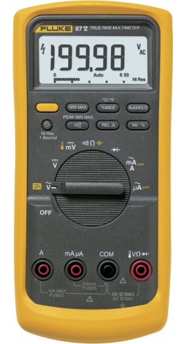
I am going to be using a standard multi-meter as is shown in the pics for what I do. I got this meter in my tech school tool box my first freshman year of college(not a typo) when my the 94 was still brand new and have been using it faithfully ever since. On this meter as in many other(old meters) there is the dial in the middle, a power button and then the spot for the leads in the bottom. This meter is old enough that it is not auto-ranging meaning for example if you go to the ohm section of it(with the ohm symbol/upside down horse shoe) the numbers listed in it tell the maximum reading you expect to see. If you go above it it does not explode it just tells you the reading is over the max limit and you flick the dial up a couple of notches. Modern meters you just set it to ohms and then it will automatically set the range for you but mine as I said is older then some of you reading it. Now the multiple spots on the bottom can cause confusion but its not hard. The black never moves, it stays put and if you look next to the red spots you will see the voltage symbol, resistance symbol and next to the other you will find the current symbol. For this next part we want the red lead in the resistance spot.
Have you ever held a harness in your hand and wondered what pin in it went to what wire? Here is a couple way to tell.
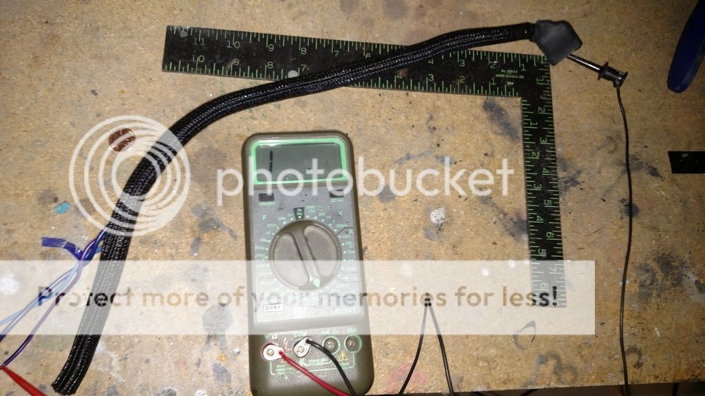
Ohm it out - In this process we are just going to be measuring the resistance of the wire. In this case it will not matter what range I set the meter to as a piece of wire should have a very low impedance, in a perfect world it would be 0. Once the dial is set its important to make sure the meter leads are plugged into the correct spot to read resistance and the ground is in the same spot it always should be. Take a look at the meter and it should read in this case "1 . " which means infinite, or no connection. Its never a bad idea to test to make sure you have things set up right and if you touch the two leads together you will see that the display changes to a regular display with a number. The number on it is not important any reading means its making a connection. When you remove the two leads, the display will again go to "1 . ". Now take one end of the leads and connect it to the pin you want to find, and now with the other lead you can try one wire at a time. If the pin does not match your wire the display will not change from the 1 . , if it is connected it will again give a regular number and once again that number is not important, it just tells us we found what wire goes to what pin.
Here it shows no connection
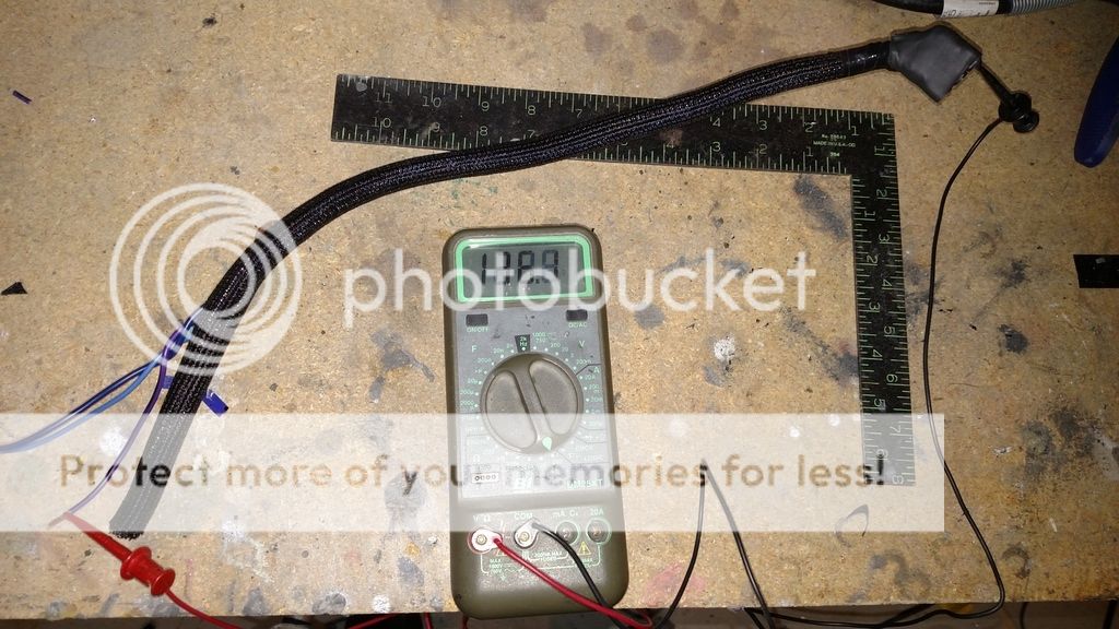
Here it shows we have found the purple wire is connected to the pin I suspected.
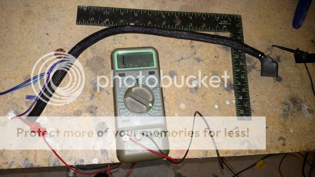
diode check - This spot on the dial is marked by the little arrow with the line on the end of it as shown in the pic. The display is going to act the same as it did in the resistance test meaning with no connection it shows "1 . " and will give a number when it connects, as well as give an audible beep. Again test this prior to starting by simply touching the leads together and the meter will beep, take them apart and it stops = meter is good.
This shows when its not connected and would not be beeping.
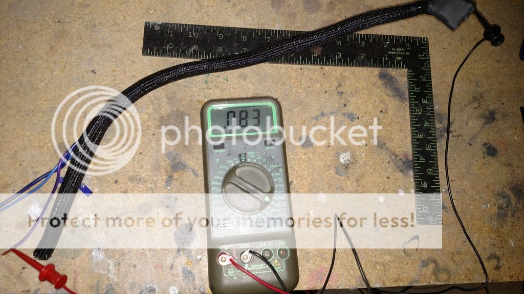
Now the test goes the same as the resistance test as well with one lead on the suspected wire, and the other on the pin. If the meter doesn't beep then switch one of the leads to a different wire/pin and keep doing this till it does beep. This way is nice because you do not have to see the display to know when its correct.
What happens if you can't reach both ends of the harness? This happens fairly often and when it does first check all the wires you suspect goes to the pin you need and confirm that they are not connected to power/ground. If they are not then take the pin you suspect and ground it to the chassis. Now go back to the wire your looking at and connect one end of the lead to the wire, and now the other lead to ground. If it is correct the meter will beep and you can confirm it by removing the ground and the beep will stop. You found the wire/pin.
reading the tutorial will give a you a start to your meter and hopefully help you to gain a little confidence to make the readings with your meters. With that being said I have to do that stupid thing to protect me and the site and say we are not responsible for any incorrect readings or damage that is done. There are more then a few meters and they each have their good/bad points I will go over for you.
So to sum it up on test lights, they are fast/cheap/easy. You also need to be
-Test lights and circuit testers-
These have long been known as the cheapest and easiest way to check for voltage. They do not check resistance, current or any of the other things that a regular meter can test for but it makes checking voltage really easy.
1.) - Here is a perfect example of how easy it is with a test light. This is the most simple version and as you see its nothing more then a 12v light. Slightly more complex designes will have some leds in it to show 6/9/12 volts. They often they look like a screw driver
with a light in it and a ground cable that comes out the back. This one would go for $10-15.
Stick with me on this as its still early in the process and there are a lot of little stuff to cover. If there is/are particular spots you want too see please pint thrm
they can start out at really cheap around $20 but get up in price pretty quick for $100+ and they will work just fine for voltage. this is the one I use and love. Its small and has a nice light on the end.
never seen this on before and it seems nice and simple.
and then some of the higher end test lights do what the other do but also give you the option to put +/- on the wire your testing to actuate for example the door locks to test if they are working.
ok so those are the general types unless you get into some super high end piece that can do much much more and cost more. I have been considering getting one but not sure I would use it all.
So lets go over the test lights pros/cons.
Pro - super easy to use an read. If it isn't reading correctly then then check the ground or the connection. Because of the simplicity of these its either the connection or the bulb.
Pro - cheap
pro - easy to find.
pro - very comfortable tool that is easy to read and understand
Cons - they will only tell you voltage unless you get one with smaller multiple leds to show what the voltage is, otherwise it reads either on or off.
Cons - its a VERY comfortable tool right up till it slips from the wire and stabs you!
cons - they say that most are not computer or air bag safe. I am not really sure what to think about this as I have talked to a lot of installers about it and no one actually knows anyone that has either popped the air back or smoked the ECU. There is no reason to probe/test a ai bag and a meter really is a better tool if you are measuring at the computer. So use some common sense as these are really just to make quick/easy tests and not meant to be the only meter/tester in your box.
Newly added 12/28/2017
I am going to be using a standard multi-meter as is shown in the pics for what I do. I got this meter in my tech school tool box my first freshman year of college(not a typo) when my the 94 was still brand new and have been using it faithfully ever since. On this meter as in many other(old meters) there is the dial in the middle, a power button and then the spot for the leads in the bottom. This meter is old enough that it is not auto-ranging meaning for example if you go to the ohm section of it(with the ohm symbol/upside down horse shoe) the numbers listed in it tell the maximum reading you expect to see. If you go above it it does not explode it just tells you the reading is over the max limit and you flick the dial up a couple of notches. Modern meters you just set it to ohms and then it will automatically set the range for you but mine as I said is older then some of you reading it. Now the multiple spots on the bottom can cause confusion but its not hard. The black never moves, it stays put and if you look next to the red spots you will see the voltage symbol, resistance symbol and next to the other you will find the current symbol. For this next part we want the red lead in the resistance spot.
Have you ever held a harness in your hand and wondered what pin in it went to what wire? Here is a couple way to tell.
Ohm it out - In this process we are just going to be measuring the resistance of the wire. In this case it will not matter what range I set the meter to as a piece of wire should have a very low impedance, in a perfect world it would be 0. Once the dial is set its important to make sure the meter leads are plugged into the correct spot to read resistance and the ground is in the same spot it always should be. Take a look at the meter and it should read in this case "1 . " which means infinite, or no connection. Its never a bad idea to test to make sure you have things set up right and if you touch the two leads together you will see that the display changes to a regular display with a number. The number on it is not important any reading means its making a connection. When you remove the two leads, the display will again go to "1 . ". Now take one end of the leads and connect it to the pin you want to find, and now with the other lead you can try one wire at a time. If the pin does not match your wire the display will not change from the 1 . , if it is connected it will again give a regular number and once again that number is not important, it just tells us we found what wire goes to what pin.
Here it shows no connection
Here it shows we have found the purple wire is connected to the pin I suspected.
diode check - This spot on the dial is marked by the little arrow with the line on the end of it as shown in the pic. The display is going to act the same as it did in the resistance test meaning with no connection it shows "1 . " and will give a number when it connects, as well as give an audible beep. Again test this prior to starting by simply touching the leads together and the meter will beep, take them apart and it stops = meter is good.
This shows when its not connected and would not be beeping.
Now the test goes the same as the resistance test as well with one lead on the suspected wire, and the other on the pin. If the meter doesn't beep then switch one of the leads to a different wire/pin and keep doing this till it does beep. This way is nice because you do not have to see the display to know when its correct.
What happens if you can't reach both ends of the harness? This happens fairly often and when it does first check all the wires you suspect goes to the pin you need and confirm that they are not connected to power/ground. If they are not then take the pin you suspect and ground it to the chassis. Now go back to the wire your looking at and connect one end of the lead to the wire, and now the other lead to ground. If it is correct the meter will beep and you can confirm it by removing the ground and the beep will stop. You found the wire/pin.