Ditching the push/pull headlight knob

OP
OP
JeremyAlan

JeremyAlan

SN95 Supporting Member
Joined
Apr 1, 2006
Messages
2,156
Reaction score
22
Location
Suffolk, England
Looks nice, great idea. I love stuff like that. Like you, I'm not really a fan of the current light switch. Looking forward to the progress! For around the switch, if you didn't want to do all the bondo stuff, you could get a trim ring made, maybe in aluminum. Leave it bare if you are into that, or paint it black to blend?

I like that idea a lot. They make this switch with faux-chrome on it if you had billet accents in the car to match. I don't and I'm wrapping mine in suede :)


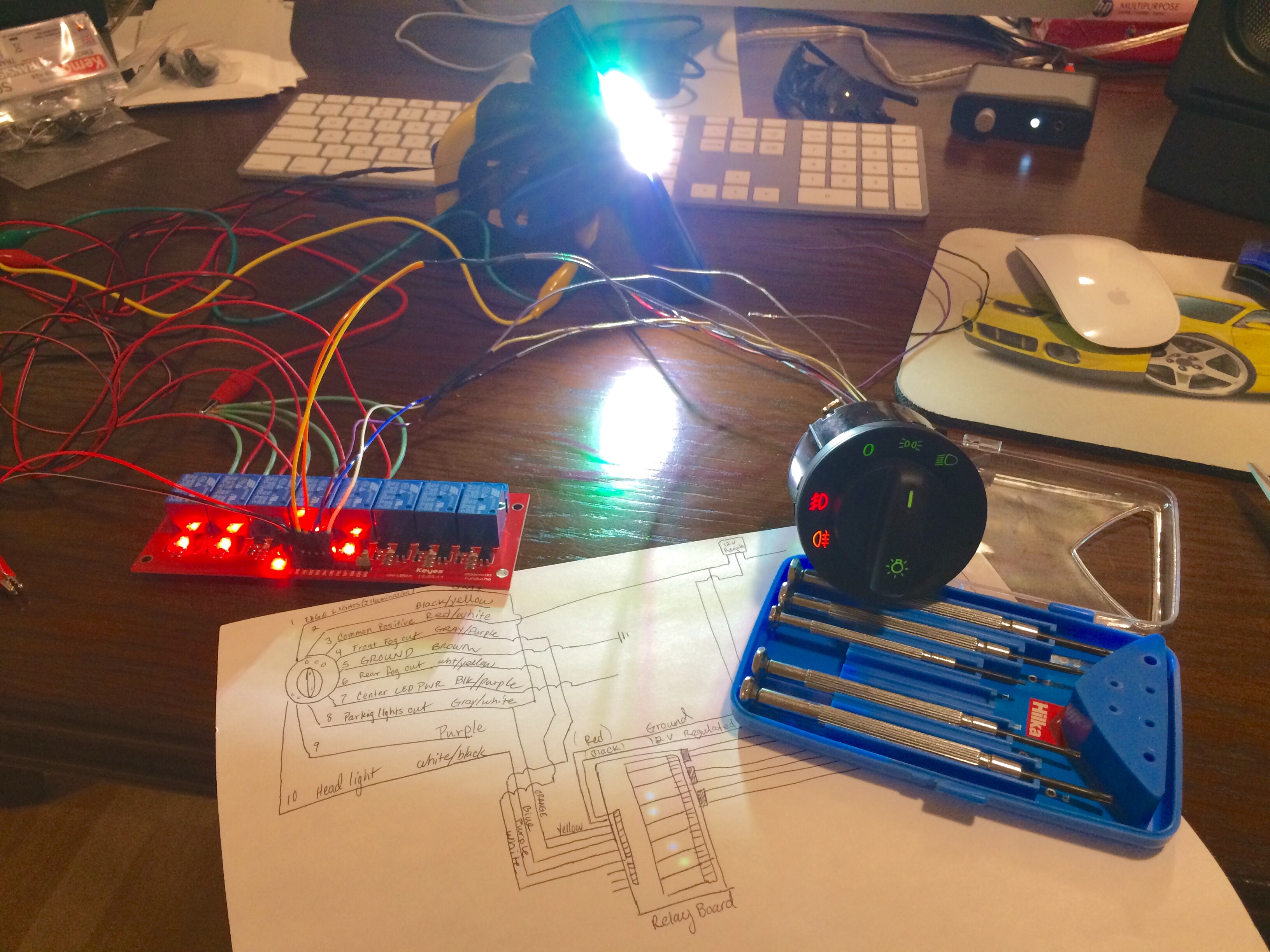
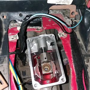
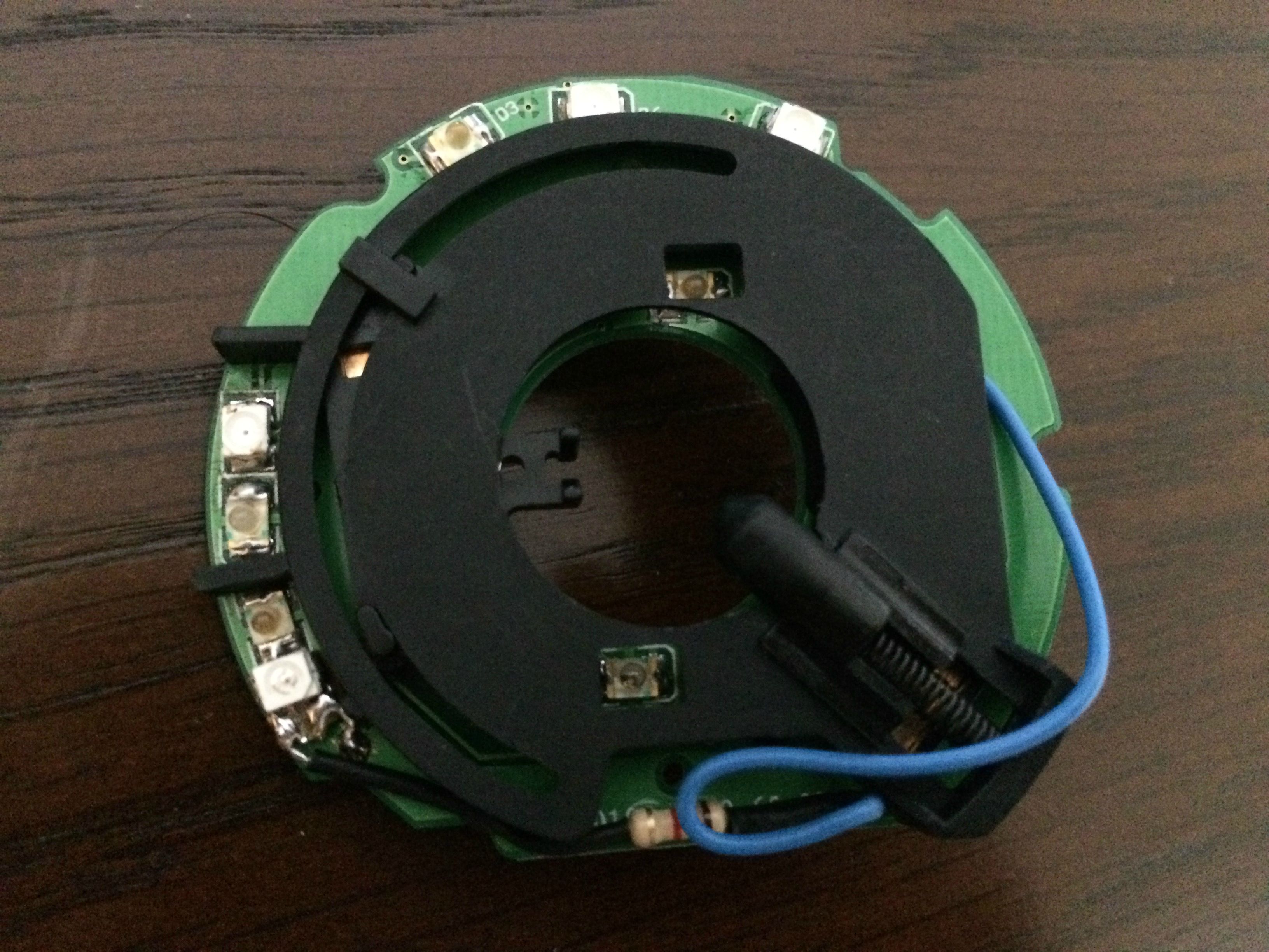
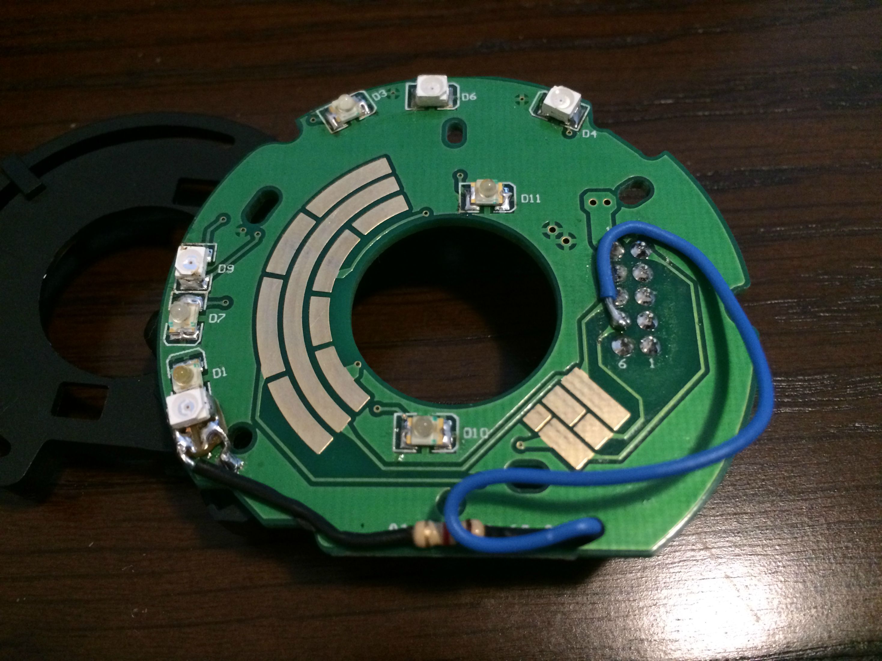
So, quick update guys. I burnt up one switch already... I wasn't thinking of the small traces on the PCB and temped some wires together to try the first switch out because I was excited. I fried the PCB lol. Oops! Lesson learned: there is a reason the Mustang wiring is a much heavier gauge than the wires coming out of the VW headlight switch lol. So, ordered a new switch and sent it off to my buddy that does the PCB soldering for the leds. He swapped them over to green-yellow to match the Cobra's interior and we had a lack of indication on the stock gauge for rear fog. I had him add a wire and a spare piece of pcb he had laying around so that we could add our own red led for rear fog -- as seen in the next two photos.

QxWm9IG.jpg


Cla1oU6.jpg


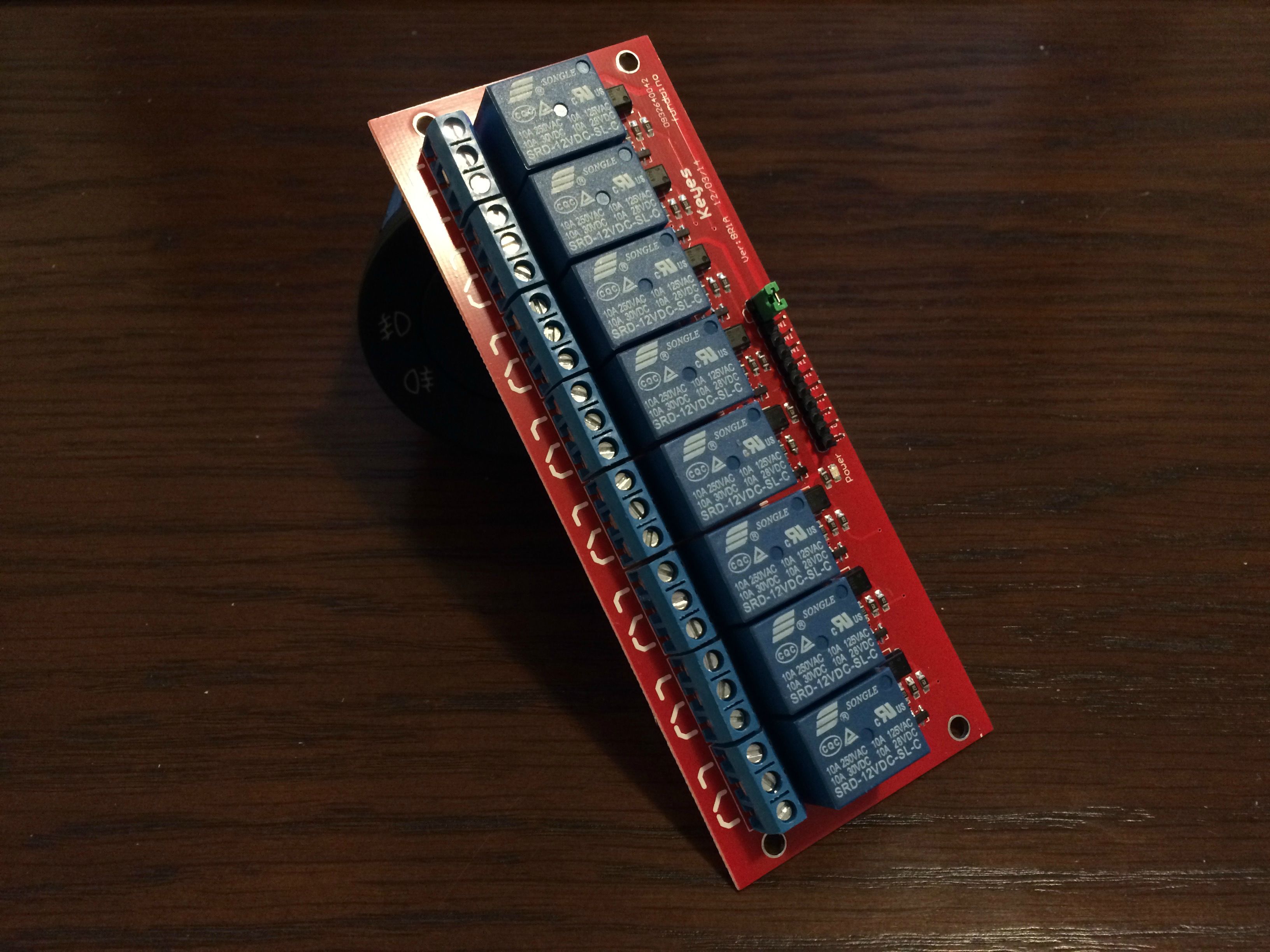
Finally, here is my answer to the INSANE POWER of the Mustang's wiring. lol. I found this relay board on a uk raspberry pi/arduino website. It can accept between 5-12v(which i will regulate into the switch and in turn to the board) and the relays can handle 10 Amps. I figure the heavy power draw stuff already has it's own relays(ie-headlights). I picked one with 8 relays because I need one relay per function on the switch(Illumination, parking lights, headlights, front fogs, and rear fogs + room for possible expansion). I like the packaging of this option over standard automotive relays(40A). I can mount it in a plastic enclosure behind the dash and tuck it away nicely.

TzOyAsL.jpg
 

ttocs

Post Whore
Joined
Oct 9, 2009
Messages
32,650
Reaction score
5,664
Location
Evansville Indiana
I'm thinking about building up a contour below the switch with some bondo and working the shape with some sandpaper(trying to make it look like ford put it there). The whole gauge surround is getting covered in Alcantara when I'm done.

You would be better off using plastic-weld or some kind of epoxy. Bondo works but it can chip off so unless I am putting it into a corner I use epoxy. If its going to be wrapped later you may need to open the hole up a little bit to get it in the hole and the switch as well. If you do build up a spot to keep the filler off the switch and make it easier to get the space needed for the wrap use double stick tape(the thicker foam kind) around the switch. Its thickness will keep the filler back enough to allow for the material to wrap easier and with less sanding.
 
OP
OP
JeremyAlan

JeremyAlan

SN95 Supporting Member
Joined
Apr 1, 2006
Messages
2,156
Reaction score
22
Location
Suffolk, England
You would be better off using plastic-weld or some kind of epoxy. Bondo works but it can chip off so unless I am putting it into a corner I use epoxy. If its going to be wrapped later you may need to open the hole up a little bit to get it in the hole and the switch as well. If you do build up a spot to keep the filler off the switch and make it easier to get the space needed for the wrap use double stick tape(the thicker foam kind) around the switch. Its thickness will keep the filler back enough to allow for the material to wrap easier and with less sanding.

Yeah, I emailed Redlinegoods and they said to leave 1/8th of an inch around the switches for leather and 1/16th for suede. Thanks for the protip on the bondo!
 

ttocs

Post Whore
Joined
Oct 9, 2009
Messages
32,650
Reaction score
5,664
Location
Evansville Indiana
Looking at the pic more it looks like the top might be a little lower then the dash and need the top to be dish/concave to meet the switch? I would think it might look a little funky with the top dished and the bottom raised up. You might be better off setting the switch back just enough so the bottom is flush or slightly dished and then do the same all the way around. It will take more work of course but I think in the end it would give it a little more natural look. I can think of a way it might work if you want to try it.
 
OP
OP
JeremyAlan

JeremyAlan

SN95 Supporting Member
Joined
Apr 1, 2006
Messages
2,156
Reaction score
22
Location
Suffolk, England
Looking at the pic more it looks like the top might be a little lower then the dash and need the top to be dish/concave to meet the switch? I would think it might look a little funky with the top dished and the bottom raised up. You might be better off setting the switch back just enough so the bottom is flush or slightly dished and then do the same all the way around. It will take more work of course but I think in the end it would give it a little more natural look. I can think of a way it might work if you want to try it.

There is a lip on the dash pad just above the 10-11 o'clock position of the switch(the gauge surround rests on it when installed). I'm not sure if there is much room to take the gauge surround down to meet the switch. Also, The switch is just sitting there in the photos. I have control over the depth of the mounting.

Here is a guy who beat me to the punch :) He used a 09 Ford fusion switch. He ran into the backlight color problem that I did. Ford used a blue-green lighting scheme on their newer cars(think 2010+ interior lighting) and it doesn't match the stock color. He used bondo and it looks good once painted.

Username 04redfireRO on SVTP


97NYstanGT

Active Member
Joined
Dec 5, 2009
Messages
281
Reaction score
0
The original push/pull knob also dims the lights on your dash, how are you gonna go about that?


Sent from my iPhone using Tapatalk
 

ttocs

Post Whore
Joined
Oct 9, 2009
Messages
32,650
Reaction score
5,664
Location
Evansville Indiana
its different but looks a bit strange to me now that I can see it. I am going to shave my switch and modify the rear window defroster switch to do the lights. I don't get frost on the window anyway and I think It will make for a smooth look to it.
 

lutter94

Well-Known Member
Joined
Apr 11, 2008
Messages
3,060
Reaction score
172
Location
South Dakota
If someone were to ditch the defroster switch, fill it in, then lower the round switch to fill the space better, I'd think it would look pretty decent. The curves of the trim make it look a little off to me. Idk.
 
OP
OP
JeremyAlan

JeremyAlan

SN95 Supporting Member
Joined
Apr 1, 2006
Messages
2,156
Reaction score
22
Location
Suffolk, England
The original push/pull knob also dims the lights on your dash, how are you gonna go about that?


Sent from my iPhone using Tapatalk

I mentioned earlier in the thread about using a dimmer from another car. However, my SVT cluster is EL-glow and has never been too bright(sometimes, not very bright at all), so I'm just wiring it straight through at max brightness lol. It will be permanent. I also took the bulb out of my dome light and rely on my footwell lights for the dome circuit, so I would never need to "twist-for-dome" either.

its different but looks a bit strange to me now that I can see it. I am going to shave my switch and modify the rear window defroster switch to do the lights. I don't get frost on the window anyway and I think It will make for a smooth look to it.

Just keep in mind the factory hole and contouring of the plastic. That's why mine is where it is. Plus there is a ton of dash structure behind that area where the defrost button is. Lot's of hacking away.

If someone were to ditch the defroster switch, fill it in, then lower the round switch to fill the space better, I'd think it would look pretty decent. The curves of the trim make it look a little off to me. Idk.

See above
 

Witzy0070

Active Member
Joined
Dec 10, 2009
Messages
836
Reaction score
2
Location
Montana
Now there is some grade A workmanship. Job well done sir.

A perfect example of nothing exceeds like excess!

I do not like the way it looks, seems bloated. How do you like the finished product?
 

ttocs

Post Whore
Joined
Oct 9, 2009
Messages
32,650
Reaction score
5,664
Location
Evansville Indiana
The dimmer should not be a big deal to hack and modify. It is just a variable resistor or potentiometer is the tech name. You can probably remove the stock pot or just measure it and find a replacement to put maybe under the dash or even in the coin holder in the console or something.
 
OP
OP
JeremyAlan

JeremyAlan

SN95 Supporting Member
Joined
Apr 1, 2006
Messages
2,156
Reaction score
22
Location
Suffolk, England
More progress! Bench tested the switch and relay board together and everything is working great! I'm just waiting on a enclosure for the relay module and then it will go in the car.


ida1ZdZ.jpg
 
OP
OP
JeremyAlan

JeremyAlan

SN95 Supporting Member
Joined
Apr 1, 2006
Messages
2,156
Reaction score
22
Location
Suffolk, England
Update:


I have everything working on the bench(my dining room table-lol) and will have it wired in the car soon. Here is a video of everything functioning.


[video=youtube;CXZ5Bf4bMPs]https://www.youtube.com/watch?v=CXZ5Bf4bMPs[/video]


The green LED represents the illumination circuit, then each white LED after that represents: parking lights, headlights, front fog and rear fog circuits. I'm very happy with how it's turning out.


Song is by Lower than Atlantis and is called Criminal
 

97NYstanGT

Active Member
Joined
Dec 5, 2009
Messages
281
Reaction score
0
Wow, some impressive electrical skills, I love it. Time to install it


Sent from my iPhone using Tapatalk
 

LaserRed95GT

Member
Joined
Jan 22, 2013
Messages
217
Reaction score
1
Next you should make the stock defroster button below the headlight knob into a push to start button...atleast I would if I was this could withwiring.
Nice work though! Looks great.

too bad I prefer my retro pull out knob ;)
 
OP
OP
JeremyAlan

JeremyAlan

SN95 Supporting Member
Joined
Apr 1, 2006
Messages
2,156
Reaction score
22
Location
Suffolk, England
I'm about to necro the shit out of this thread.

So, finally got into a position where I can work on the car and it runs. Long story short, the alternator went out in the fall and I was just mad at the car, so I made no progress.

The old relay board is gone and has been replaced with a much better setup. The old one wasn't going to cut it and I was having to make too many concessions to make it work. So, I decided to go a different way.

90db7657a4c3e45f6d57bc0b03d5257f.jpg


This modular system holds six micro relays that are 25A each. That should be plenty for all the lighting circuits. I have a friend with a laser etcher, so I decided to church up the relay holder a little bit to help myself ID each relay down the road. This was that result:

06f20baf09432af98d82faee4ef9b6f7.jpg


And finally, some laser etcher porn:

https://youtu.be/F_uR5Yd1eHo

I should be able to have this installed and working this weekend.
 

o36

New Member
Joined
Sep 13, 2016
Messages
50
Reaction score
0
DUDE. So sick! My knob finally bit the dust and if I forget, and pull just slightly too hard when turning on the lights off comes the knob. Total pain in the ass, and this looks so sick.

If you could put together a DIY guide for the project I'd do one to my car, I just can't engineer for shit.
 

Forum statistics

Threads
77,513
Messages
1,504,091
Members
14,981
Latest member
Cwacaser

Members online

Top