Wiring diagram:
http://diagrams.hissind.com/wp-content/uploads/2011/06/Instrument-cluster-Wiring-Diagram.gif
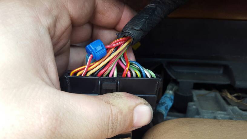
the red/white wire you grounded is the signal wire to the temp sensor, why your fuel gauge began working at that point is beyond me.
What i would do, is test the resistance between the red/white wire and ground (with it Not grounded as you have it now). This Should give you a resistance value. Then start the car and allow it to heat up (or turn it off and allow it to cool down) the resistance value Should change as the coolant temp changes. If it does, you can eliminate the wiring frok the cluster to the temp sensor, temp sensoe and the wiring from the temp sensor to ground as the problem.
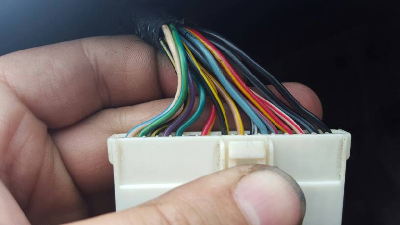
Then i would test the orange/yellow wire from the pin to ground for continuity.
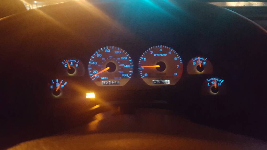
The temp gauge i believe works from a variable resistor (temp sensor) with a known resistance (a value built into the gauge itself) as the coolant temp changes, the gauge changes due to the temp sensor value changing.
*update-
i believe i know why your fuel gauge now works and the temp gauge doesnt.
If you added the ground wire between the red/white wire at the cluster (with the blue splice) then it uncovered your problem!
if you have a break in the ground After the point where the orange/yellow and black/white wires come together, then neither gauge will work. By placing the ground on the red/yellow, the temp gauge wont work properly bc the ground for it is on the wrong side of the temp sensor BUT the fuel gauge will now be given a ground path to work through.
So based on that, i would test for continuity on the orange/yellow wire to chassis ground.