The resistor has nothing to do with the spedo/odo. [mention]Werecow [/mention]
Sent from my iPhone using Tapatalk
Sent from my iPhone using Tapatalk
This is the chip on the speedo. It is a 5 NOR input.It may be the weekend before I can pull my cluster again. That would be awesome if you could explain how to bench test it. Also, what chip are you talking about exactly? Thanks
Sent from my iPhone using Tapatalk

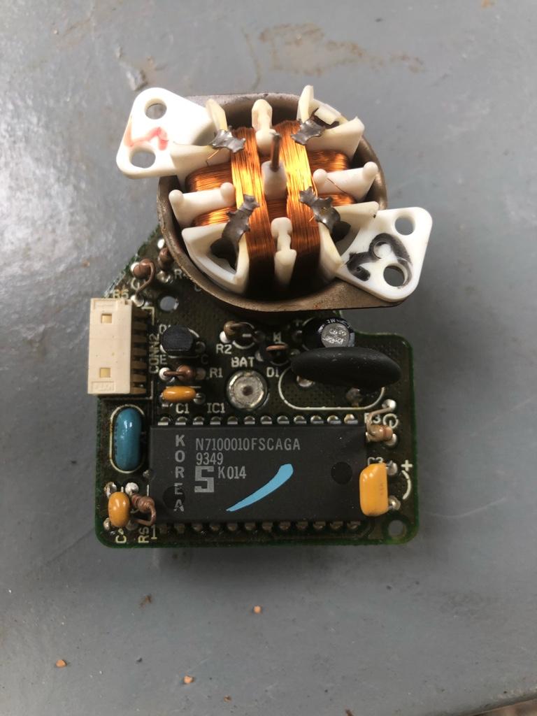
This is the chip on the speedo. It is a 5 NOR input. View attachment 5926
I checked the other components. The only remaining components not checked are the chip and X1. I’ll have to pull the crystal to see it’s frequency. The chip is a Signetics. No longer made, but some stock is out there, albeit for $42 each. There is a Philips chip of the same number, but comes from China. $3 with $25 shipping.
To remove the needle, pull the stop pin out and let the needle come to rest. I think you’ll find it ends up about 6 o’clock. Then pull the needle off. Straight pull and takes a little effort. It will come off.
Oh, I just noticed your board is lacking the two bipolar electrolytic caps. Was that from a 120 mph speedo for a 6 cylinder?
FYI, for all the gauge needles that lose adjustment when disconnected, I’ve always found the easiest way to get them back to normal is leave the lens cover off, with the needles just barely on, start the vehicle. You can adjust the oil pressure and volts to wherever they normally would be, once the car is at normal operating temp, adjust that needle and then press it into position. For your speedometer, use your gps function on phone to tell you how fast your going, then adjust your needle to match.
Just pull straight off is the best advice I can give you. Mine stabilized at the 6 o’clock position before I pulled it. I’ll worry about calibration when it goes back.
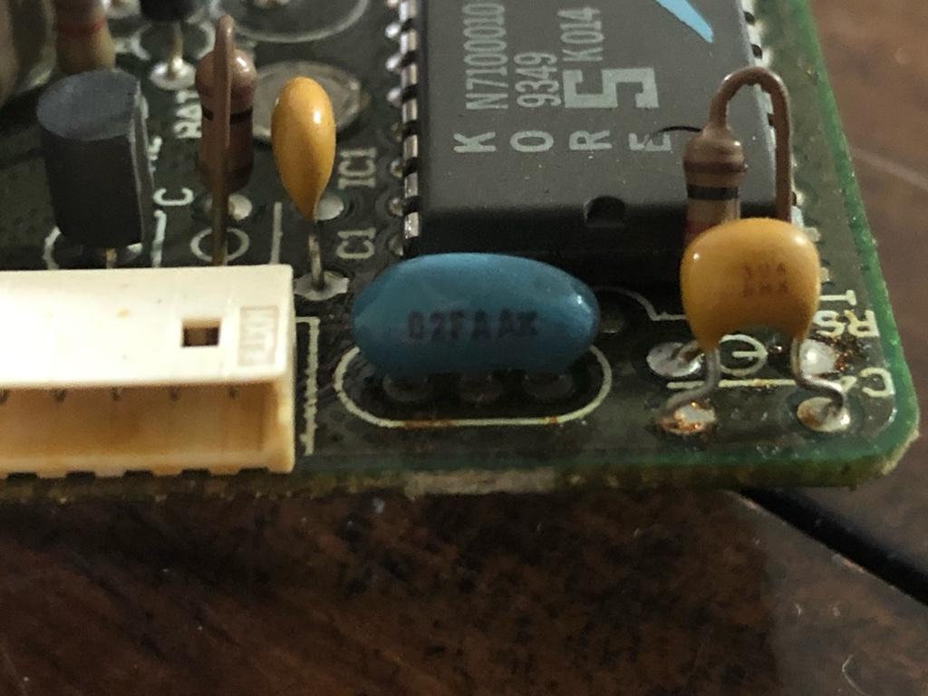
I haven’t confirmed my cluster is dead, yet. I just tested all the other components except the chip and that blue crystal labeled X1, just left of the chip. The other components are rather robust and I had a leaky capacitor that I replaced. It was not the problem, though.
I need to verify the chip is bad by putting the correct ac signal to the speedo input, the ‘sig in’ on the back. I need to get the sensor out of the transmission in order to spin it up on the bench and provide the correct signal for a test to verify my board is either good or bad. If bad, it must be the chip.
Can you photograph the blue component to the left of the chip and post? I see yours has the value printed on the left where it can be seen. That will let me see the frequency reference.
Ok, I pulled the speed sensor and applied the input to my speedometer board. No signal getting to the coils, so the chip or the crystal frequency reference (X1) is bad. I’m betting on the chip.
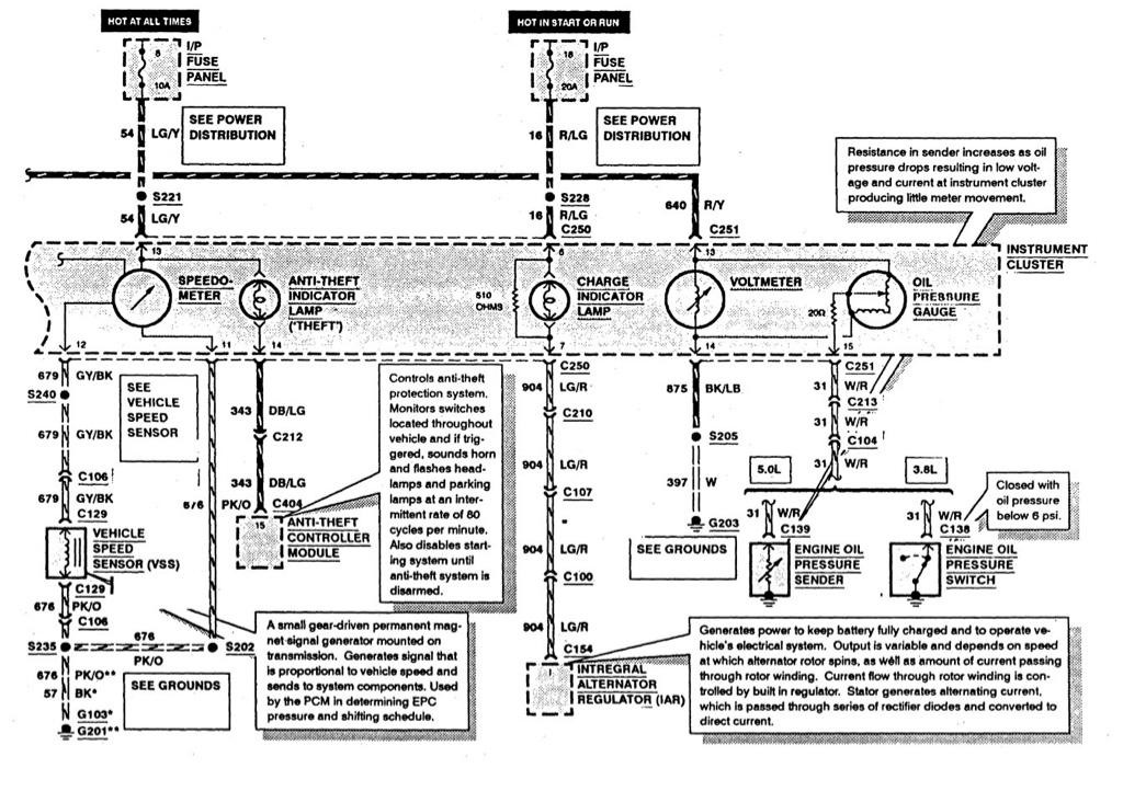
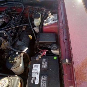
Excellent questions, Ryan. I have looked for the grounds and haven’t found them, yet. I would love to know, as well. C106 is the connector under the hood on the firewall in front of the passenger seat. You can trace the wires to that connector on the way to the ECM, I think. My cruise control worked, but I was also having trouble getting the AC signal on pins 11 and 12. I could reference the voltage against another ground, however. It looked like my pin 11 and other grounds on C250 were bad. It’s a frustrating combination to chase down.
Have you tried to use your cruise control to see if it works. If so, the speed sensor is functioning and the signal is getting to the ECM. Now, to test for signal to the C250 connector, connect a voltmeter for AC voltage across the pins for the signal at the connector, pins 11 and 12. You should see a voltage up to 7-9 volts, but more like 2-3 volts around 20-30 mph. If the signal is there, then your wiring should be good and the speedometer board is suspect. You can measure the resistance of the coils in the motor on the board. They should be around 187 ohms if good. S- to S + and C- to C +.
I am located in TX in the DFW area. I’ll let you know if I get those chips. I’m looking for a junker similar type Ford cluster from a similar year instrument cluster in other models right now and having difficulty finding any repair shops that will answer the phone to see if they have a lead on this chip.
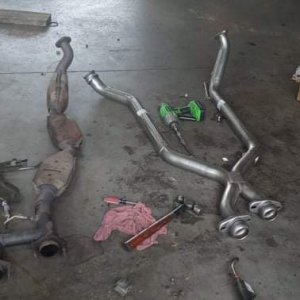
Chek the gear in the speedometer cable where it connects to the transmission just in case the issue is mechanical. It will take 10 minutes or less...
In case it needs to be replaced:
https://lmr.com/products/Mustang-Speedometer-Gear-Calculator