OLD FARTS "It never ends"

OP
OP
OLD H2S

OLD H2S

Well-Known Member
SN95 Supporter
Joined
Jul 4, 2015
Messages
1,190
Reaction score
232
Location
Silver Spring Maryland
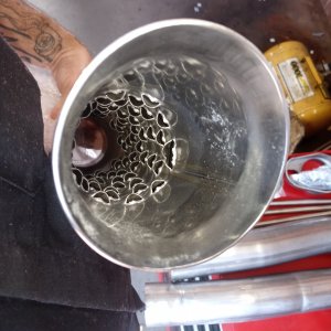
I do not know yet, I have only done number 1 cylinder to check the valve interference and the valve is not even touching the clay? How could I screw this up?
 

96blak54

Moderator
Staff
Joined
Feb 21, 2011
Messages
10,040
Reaction score
2,880
Location
In the shop
Man im only asking. Be like a "check list". Not trying to badger you. Did you use different valves? Mash the valve inyo the clay, checking lift measures while doing it.
 
OP
OP
OLD H2S

OLD H2S

Well-Known Member
SN95 Supporter
Joined
Jul 4, 2015
Messages
1,190
Reaction score
232
Location
Silver Spring Maryland
Badger on I need it, helps me remember what I should be doing. I was using a solid checking lifter and it was lifting the valve off the seat?
I put in a regular type lifter and pushed down to check the clearance between the roller and cam and got .023 and the spec is .016 to .032 so my valve stem height is right in the middle of the spec. I built up the clay and still did get any mark in it so I am assuming my duration is so low as to not be a concern which in itself is a concern. After cutting .080 off the heads and block and no interference, amazing. I looked for cam simulation apps but they are all 100 bucks and up so I think I will use a bigger wad of clay.
 
OP
OP
OLD H2S

OLD H2S

Well-Known Member
SN95 Supporter
Joined
Jul 4, 2015
Messages
1,190
Reaction score
232
Location
Silver Spring Maryland
I had to cut down the solid test lifter about 10 times to get it to zero out and then I got a good test mark in the clay to measure. I have a ton of room, I could retard the cam some...
IMG_0716-D.jpg
IMG_0717-D.jpg
 
OP
OP
OLD H2S

OLD H2S

Well-Known Member
SN95 Supporter
Joined
Jul 4, 2015
Messages
1,190
Reaction score
232
Location
Silver Spring Maryland
I made up 2 extended chain tensioner extenders but doing the mock up the drivers side chain is is not as loose as the right side is? I think some adjusting is in order.
IMG_0718-D.jpg
 
OP
OP
OLD H2S

OLD H2S

Well-Known Member
SN95 Supporter
Joined
Jul 4, 2015
Messages
1,190
Reaction score
232
Location
Silver Spring Maryland
I had to scrounge around for a 12 point 7/16 1/2 drive socket to torque the connecting rods. Then on to what to torque a used set of "03 Cobra rods, lots of numbers out there from Manley, ARP, you,me.. with oil, with graphite torque lube, lots and lots of advice. I settled for the measure the stretch of the bolt method for the used bolts as the best way to get the right preload stretch no matter what the torque number came up to. I did not have the cool custom tool to use so I used an old caliper that had a dead magnetic zone in it and welded on some pins to match the pics on the web and bang zoom good to go. The bolts are 1.720" long and .005 to .006 is a good zone for used bolts and that was 50 LBS of torque coming up 5 pounds at a time.
IMG_0719-D.jpg
IMG_0721-D.jpg
IMG_0723-D.jpg
 
OP
OP
OLD H2S

OLD H2S

Well-Known Member
SN95 Supporter
Joined
Jul 4, 2015
Messages
1,190
Reaction score
232
Location
Silver Spring Maryland
OH CRAP!!!!! Did I put the little oil plugs back in the bottom of the heads??? I was looking at the tear down pics on the 2V tech thread I have and I might have forgotten to put the plugs back in.
IMG_0494-D.jpg
 
OP
OP
OLD H2S

OLD H2S

Well-Known Member
SN95 Supporter
Joined
Jul 4, 2015
Messages
1,190
Reaction score
232
Location
Silver Spring Maryland
I left the plug out. BUT, it is on the outside bottom of the head, just really hard to get to. I cut down an Allen head wrench and it was easy. I just get a new one.
 
OP
OP
OLD H2S

OLD H2S

Well-Known Member
SN95 Supporter
Joined
Jul 4, 2015
Messages
1,190
Reaction score
232
Location
Silver Spring Maryland
Here's the proof you can put in the Maximum Motorsports roll bar without cutting up the rear side panels, it was not fun....
IMG_0738-D.jpg
This is the bottom stiffening plate for the roll bar. I welded it in and added tie in bars to the Steeda subframe connectors. Now I have a strong place for a jack point and the roll bar is welded to the sub frame.
IMG_0735-D.jpg
 
OP
OP
OLD H2S

OLD H2S

Well-Known Member
SN95 Supporter
Joined
Jul 4, 2015
Messages
1,190
Reaction score
232
Location
Silver Spring Maryland
A lot of wiggling around and a big brass hammer to seat the second back bar, the first bar goes in easy. I did by myself and I was dripping and worn out by the time I was done.
 

neverenuff

Active Member
Joined
Nov 23, 2015
Messages
510
Reaction score
7
Here's the proof you can put in the Maximum Motorsports roll bar without cutting up the rear side panels, it was not fun....
IMG_0738-D.jpg
This is the bottom stiffening plate for the roll bar. I welded it in and added tie in bars to the Steeda subframe connectors. Now I have a strong place for a jack point and the roll bar is welded to the sub frame.
IMG_0735-D.jpg
Looking good! The pvc that comes with the MM kit wasn't even close to square up the hole for the rear supports, however your install came out great! What side is that square tubing if you don't mind?..like to link my subframes to the bottom of the roll bar mount plate.

Sent from my SM-G935V using Tapatalk
 
OP
OP
OLD H2S

OLD H2S

Well-Known Member
SN95 Supporter
Joined
Jul 4, 2015
Messages
1,190
Reaction score
232
Location
Silver Spring Maryland
It is 1 1/4 " with 1/8" wall.
IMG_0741-D.jpg

Here is what I did today, I coped the round 1 3/4" diagonal cross brace to the overhead main bar. The angle is holding up the tubing while I make little marks on it to remove and then test fit again and again. The big cable is the negative battery connector. Next up is cleaning up the weld spatter and the seam sealer and some SEM trim paint.
IMG_0740-D.jpg
 
OP
OP
OLD H2S

OLD H2S

Well-Known Member
SN95 Supporter
Joined
Jul 4, 2015
Messages
1,190
Reaction score
232
Location
Silver Spring Maryland
Here is a shot of the rear seat delete installed, a little more trimming and it will be done.
IMG_0742-D.jpg
Next is mocking up the rear Cobra brake kit from FTR.
IMG_0743-D.jpg
 
OP
OP
OLD H2S

OLD H2S

Well-Known Member
SN95 Supporter
Joined
Jul 4, 2015
Messages
1,190
Reaction score
232
Location
Silver Spring Maryland
The rotor in the pic above is the Baer 13" which really is 13" in diameter and rubs on the outside edge. This pic is the Cobra front rotor which is 12.88" in diameter and have just a little clearance and do not rub. This wheel is 18" and 45mm backspace.
IMG_0744-D.jpg
This shot is the stock 17" with 35mm backspace.
IMG_0746-D.jpg
This one is the 18X10, lots of room.
IMG_0749-D.jpg
 
OP
OP
OLD H2S

OLD H2S

Well-Known Member
SN95 Supporter
Joined
Jul 4, 2015
Messages
1,190
Reaction score
232
Location
Silver Spring Maryland
I'm back, Thanks to the ADMIN. they are shaking their heads at my dumb mistakes. I got a real mess on my computer trying to download a PDF of how to rebuild a T45 transmission. Took a week to clear out all the contaminates and it really messed up this site for me. So you missed the tranny rebuild in all it's glory and faults as I put it back together with new parts. Not all that hard to do but the sequence has to be right and I would get too far ahead on one shaft and have to take it back apart to put a corresponding part on the other shaft in the right order. But all is good and here is a pic. of the problem that required the clutch needing to be adjusted every 4 days that started the whole rebuilding of the car in the first place.
IMG_0832-D.jpg
 

96blak54

Moderator
Staff
Joined
Feb 21, 2011
Messages
10,040
Reaction score
2,880
Location
In the shop
The T45 are easy rebuildables. Eaton lock ring pliers, mallet, few odd end tools
 

Forum statistics

Threads
77,513
Messages
1,504,084
Members
14,981
Latest member
Cwacaser

Members online

Top